This article provides a detailed description of the lost foam casting process for ductile iron castings. It includes an analysis of the process design, defect prevention, and improvement schemes. Through simulation and experimentation, the best solutions for shrinkage defect prevention are determined. Additionally, it emphasizes the importance of strengthening the process control in all procedures to enhance the internal and external quality of the castings.
1. Introduction
Lost foam casting, also known as full mold casting, is a new casting process where liquid metal replaces the disposable foam mold after cooling and solidification. This process offers several advantages such as high casting quality, low cost, and wide applicability to various materials and complex structures.
2. General Process Flow of Lost Foam Casting
The general process flow of lost foam casting for large-diameter ductile iron pipe fittings is as follows:
- Foam White Mold Production: The mold is made by processing the polystyrene foam (EPS) beads.
- Combining the Pouring System: The pouring system is fabricated using EPS foam plastic sheets.
- Assembly of the Mold Cluster: The self-processed or purchased foam molds and the gating system molds are combined and bonded together to form a mold cluster.
- Model Coating: A certain thickness of coating is applied to the surface of the solid mold to form the inner shell of the mold.
- Vibration Molding: This includes the following steps: preparing the sand bed, placing the EPS model, filling the sand, and sealing and shaping.
- Pouring Replacement: Under the thermal effect of the liquid metal, the EPS model undergoes pyrolysis and gasification, generating a large amount of gas. The liquid metal continuously occupies the position of the EPS model, advancing forward, and resulting in the replacement process between the liquid metal and the EPS model, ultimately forming the casting.
- Cooling and Cleaning: After cooling, the shakeout of the solid mold is relatively simple. The casting can be tilted out of the sand box or directly lifted out of the sand box, and the casting and dry sand separate naturally. The separated dry sand can be treated and reused.
3. Process Parameters Selection for Large-Diameter Ductile Iron Pipe Fittings
3.1 Foam Mold
The foam mold material typically uses ordinary EPS for foaming. To ensure the dimensional accuracy and rigidity of the foam mold, reduce errors and deformations caused by multiple splicing, the foam mold of large-diameter ductile iron pipe fittings is generally composed of four parts (socket part, spigot part, pipe body part, and flange part), and is formed by cold bonding. Considering the large size of the casting, the foam mold will withstand a large force during coating and molding. The density of the foam mold is taken as 0.022g/cm³ – 0.024g/cm³. The pouring system is made of 0.020g/cm³ EPS foam plastic (EPS) plates.
3.2 Pouring System
Different placement positions of the casting in the sand box can be adopted, such as bottom injection, side injection, top injection, and stepped injection. The setting of the pouring system should consider the state of the mold in the sand box, with the principle of facilitating sand filling and compaction, forming a suitable solidification method, and being convenient for the filling of the liquid metal and the smooth discharge of the pyrolysis products, preventing the collapse and sand sticking of the mold, as well as the deformation of the mold. Based on the structural characteristics of the casting and years of on-site production experience, several pouring system schemes are designed. The specific pouring form is determined according to the specific state of the pipe fitting in the sand box. Generally, stepped, middle injection, or top injection is adopted. The cross runner and the inner runner are on the inner wall of the pipe fitting or the end face of the socket (or flange); the sprue is set at the intersection of the cross runner. The ratio of the sprue to the cross runner to the inner runner is 1:(4-6):(1-2).
3.3 Coating
The lost foam casting coating is applied by the dipping method, which has the advantages of high production efficiency, coating saving, and uniform coating. However, due to the low density of the foam mold (differing by dozens of times from the density of the coating) and its low intrinsic strength, the dipping method is only suitable for small and medium-sized pipe fittings where the mold can be immersed or semi-immersed. For large-diameter foam plastic molds of pipe fittings, methods such as spraying, brushing, and drenching have to be used for coating application. Therefore, a mud pump is installed at the bottom of the coating tank and connected to a spraying pipe, so that the coating can continuously flow out of the pipe mouth, providing a spraying function. When applying the coating, the mold is flipped to spray the coating onto each part. The mud pump and its pipeline also play a role in circulating and stirring the coating in the tank. The coating thickness is controlled at 1.0 – 1.5mm. Since the foam mold needs to be flipped during the coating process and requires multiple people to cooperate, the gating system is prone to being knocked off or damaged. Therefore, the mold and the gating system are coated separately, dried after assembly, and necessary repairs and drying are carried out for pouring. The drying temperature of the mold is 45°C ± 5°C.
3.4 Molding
The negative pressure air extraction method of the sand box adopts a combination of bottom extraction and side extraction. The dry sand selected is sea sand with a particle size of 20/40 mesh, and a combination of rain-like and flexible sand addition methods is used. This can avoid strong scouring of the model, damaging the foam mold and the coating layer. The main sand addition method is rain-like sand addition, supplemented by flexible sand addition. A three-dimensional vibration table with variable frequency is used for molding and boxing.
3.5 Pipe Fitting Anti-Deformation
Lost foam cast ductile iron pipe fittings are prone to deformation. The main causes of deformation are in the mold-making, coating, and sand filling and molding processes, resulting in non-compliant geometric dimensions of the pipe fittings. This is more likely to occur in large-diameter ductile iron pipe fittings. Therefore, measures such as using resin sand ring supports are adopted to solve the deformation problem, or a combination of internal support rings and external support steel belts is used.
3.6 Melting and Pouring
According to the ISO2531 standard, the material of ductile iron pipe fittings is generally selected as QT450-10, and the melting and ladle treatment process of the molten iron is completely controlled according to the QT450-10 material. Considering the slower cooling of the castings in the dry sand in the lost foam casting process, appropriate alloying is done to the molten iron. For the lost foam casting, due to the presence of the foam mold, a certain amount of heat will be consumed during the pouring process, so the pouring temperature of the lost foam casting is generally higher than that of the ordinary sand mold casting. Different pouring temperatures are required for pipe fittings with different specifications, models, and wall thicknesses. Due to the large contour size of large-diameter ductile iron pipe fittings, which belong to thin-walled castings, a high pouring temperature is required. However, under the negative pressure, the high-temperature molten iron is prone to penetrating into the mold sand, causing a sand sticking defect on the surface of the casting. The specific pouring temperature is determined according to the specific pipe fitting specifications; generally, the pouring temperature is controlled at 1420°C to 1460°C. During pouring, ensure that the sprue is always filled. The vacuum degree during pouring is controlled at -0.040MPa to -0.045MPa, and the pouring time is controlled at 45 to 60 seconds. The holding time after pouring is controlled at 20 to 25 minutes; the vacuum degree after pouring is controlled at -0.025 to -0.030Mpa. The out-of-box time is 120 to 150 minutes.
4. Design of Pouring System for Ductile Iron Castings
4.1 Structure Analysis
The material of the ductile iron casting is QT400-15, with a casting contour size of 430mm × 620mm × 684mm, one piece per box, and a casting weight of 180kg. Many parts of this casting have a relatively thick wall thickness, and the identified area in Figure 1(a) has a size of 183mm × 40mm × 59mm, which is prone to shrinkage holes. The part sectional views in Figures 1(b) and 1(c) show that the casting has two areas that require processing oil channels, with a total length of 510mm, and high requirements for airtight leakage pressure, and no defects are allowed inside the oil channels.
4.2 Process Scheme and Simulation
Four schemes for the pouring system of the lost foam cast ductile iron castings are designed: side-bottom injection, top injection, stepped injection, and bottom injection. The MAGMA simulation is used to compare the solidification and feeding of different schemes. The side-bottom injection simulation results are shown in Figure 2. From the observation of the solidification process, as the solidification time changes, the thinner areas solidify preferentially, and the thicker areas require a longer time for solidification. The risk level of shrinkage porosity in the intersection area of the parallel plate and the upper end face is relatively high. A hot spot area is formed inside the “U”-shaped bosses on both sides of the casting, also with a certain risk of shrinkage porosity. There is a relatively high risk of shrinkage porosity in the bottom and boss-intensive areas. The time required for the solidification process is positively correlated with the increase in wall thickness. Small slag traps have little influence on the solidification process of the upper end face of the casting, and the slag-trapping effect requires experimental verification.
The top injection simulation results are shown in Figure 3, and the areas with a high risk level of shrinkage porosity are similar to those in the side-bottom injection scheme.
The stepped injection simulation results are shown in Figure 4. Focusing on the solidification process, the risk areas of shrinkage porosity are concentrated in the interior of the “U”-shaped bosses on both sides of the casting and the intersection area of the parallel plate and the upper end face, and after the inner gate solidifies, the upper end face cannot be fed.
The bottom injection simulation results are shown in Figure 5. During the solidification process, the hot spot area on the upper end face is fed by the riser, but before the feeding channel is closed, the feeding is not completed, so both the hot spot area on the upper end face and the interior of the riser will form shrinkage porosity or shrinkage holes, with a poor feeding effect, which should be modified through calculation and experiments.
4.3 Process Experiment
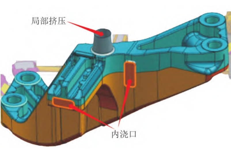
Through the analysis of the MAGMA simulation results, the bottom injection with riser pouring system is selected for the process experiment, as shown in Figure 6.
5. Defect Analysis
5.1 Main Defects
As shown in Figure 7, there are shrinkage holes on the upper end face of the casting without a feeding riser, and the positions are concentrated at the intersection of the parallel plate structure and the upper end face. Such defects are the main defects of ductile iron castings.
5.2 Cause Analysis
5.2.1 Analysis of the Cause of Shrinkage Holes
According to the MAGMA simulation results and the process experiment results, there is a shrinkage porosity defect in the bridge housing casting, located at the intersection of the upper end face and the two parallel plate-shaped structures. During the solidification process, the thick area solidifies slower than the surrounding uniform thin-walled area. After the surrounding area solidifies, the solidification process inside the thick area cannot be supplemented with molten iron, resulting in the formation of shrinkage porosity or shrinkage holes.
The solidification process of ductile iron presents a pasty solidification. In the initial stage of solidification, there is no hard shell formed on the surface. With the precipitation of graphite, the eutectic expansion pressure will lead to two phenomena: 1) The volume of the molten iron increases, and as time goes on, the solidification range continuously expands, and the final solidification area forms shrinkage porosity or shrinkage holes. The volume shrinkage during the cooling process cannot change the already formed shrinkage porosity or shrinkage holes, and may even increase the risk of shrinkage porosity. 2) The expansion pressure will directly act on the mold surface, causing adverse phenomena such as mold wall migration, mold expansion, and shrinkage porosity.
Therefore, in order to avoid the occurrence of shrinkage porosity or shrinkage holes in ductile iron castings, two control measures are proposed: 1) Appropriate feeding risers are used to feed the hot spot areas. 2) Enhance the rigidity of the mold, that is, increase the compaction degree of the molding sand, and maintain pressure continuously after pouring, with a holding time of more than 15 minutes.
5.2.2 Risers
In this experiment, risers are classified into slag traps and feeding risers according to their usage. The main purpose of using feeding risers is to supplement the molten iron and control the pressure. Figure 8 shows the three typical stages of pressure change in the riser and mold. After the inner gate solidifies, no more molten iron enters the mold, and at this time, the casting and the riser form an integral whole, as shown in Figure 8(a). When the liquid metal contracts, in the limit state of contraction, the pressure in the riser inside the mold is the smallest, as shown in Figure 8(b). With the precipitation of graphite and the formation of austenite, the expansion is characterized by the expansion of the liquid metal, thereby refilling the riser, as shown in Figure 8(c). With the continuous precipitation of graphite and austenite, the pressure inside the mold will increase, so a certain rigidity of the mold is required. When using the lost foam casting process for ductile iron castings, a suitable riser should be selected according to the structure of the casting, and at the same time, the negative pressure of the sand box during the pouring process cannot be ignored.
6. Improvement Scheme
6.1 Improvement of Riser Parameters
The modulus of the hot spot area of the casting is , the modulus of the riser is , and the modulus of the riser neck is . Referring to the design principle of the traditional sand mold casting process, two types of risers are set: 1# riser with and ; 2# riser with and . Apart from the different riser sizes, all other controllable parameters are exactly the same. Full-process trials are conducted on the two types of risers respectively, and process improvements such as anti-collision, anti-deformation, and pre-sand filling treatment are added to verify the improvement effect of different risers on the shrinkage holes at the hot spot positions of the castings.
6.2 Improvement Effect
For the lost foam casting with the bottom injection and 1# riser pouring system, there are shrinkage hole defects in the hot spot area after rough turning of the casting (within the circle in Figure 9), with a rejection rate reaching 37%, as shown in Figure 9.
For the lost foam casting with the bottom injection and 2# riser pouring system, there are no obvious defects on the upper end face of the rough-turned casting, as shown in Figure 10(b); there are no shrinkage porosity defects in the hot spot area, as shown in Figure 10(c); upon local observation, discrete small point-like defects are found on the end face, as shown in Figure 10(d). Through tracking and verification, after the full-process processing, the defects on the part end face can be removed, as shown in Figure 11.
7. Conclusion
- The pouring process for the lost foam casting of ductile iron castings selects the bottom injection and risers that match the size of the lost foam casting. Through comparative experiments combined with the structure of the product, the best solution for solving the shrinkage porosity defect is obtained.
- After determining the pouring system for the lost foam casting of ductile iron castings, it is also necessary to strengthen the process control in all procedures, prevent collisions, control the coating drying, pouring negative pressure, and holding pressure, etc., which is beneficial to improving the internal and external quality of the castings.
8. Considerations and Precautions in the Lost Foam Casting Process
8.1 Selection of Foam Beads
Three types of foam beads are commonly used for lost foam casting: expandable polystyrene resin beads (EPS), expandable methyl methacrylate and styrene copolymer resin beads (STMMA), and expandable polymethyl methacrylate resin beads (EPMMA). Commonly used expandable polystyrene resin beads (EPS) are used for casting non-ferrous metals, gray iron, and general steel castings. The bead characteristics include a semi-transparent bead, a pre-foaming multiple of 40-60, and a particle size of 0.18-0.80 mm (6 sizes). Generally, the selected original bead size is less than or equal to 1/9 – 1/10 of the minimum wall thickness of the casting.
8.2 Model Production
There are two situations: one is to make from foam beads, including pre-foaming, aging, foaming molding, and cooling and demolding. The other is to make from foam plates, involving resistance wire cutting, bonding, and forming the model. For simple models, a resistance wire cutting device can be used to cut the foam plate into the required model. For complex models, first, the model is divided into several parts using a resistance wire cutting device, and then they are bonded together to form an overall model.
8.3 Model Cluster Assembly
It is an indispensable process in lost foam (solid) casting to bond the self-processed (or purchased) foam model with the gating system model to form a model cluster. Currently, the bonding materials used include rubber latex, resin solvents, hot melt adhesives, and adhesive tape.
8.4 Model Coating
A certain thickness of coating must be applied to the surface of the solid mold to form the inner shell of the mold. The coating plays a crucial role in preventing liquid metal from penetrating into the sand during pouring and ensuring the smooth progress of the casting process. The coating should have good adhesiveness, permeability resistance, and gas permeability. When applying the coating, it is necessary to ensure that the coating is uniform and free of cracks or bubbles. The drying process of the coating also needs to be carefully controlled to ensure its performance.
8.5 Vibration Molding
During vibration molding, proper vibration parameters need to be selected. The frequency and amplitude of vibration should be adjusted according to the size and shape of the casting to ensure that the sand is filled evenly and compacted firmly around the mold. At the same time, attention should be paid to avoid excessive vibration that may damage the mold. The sand used for vibration molding should also meet certain requirements for particle size distribution and cleanliness to ensure the quality of the casting.
8.6 Pouring Process Control
In addition to the pouring temperature and vacuum degree mentioned before, the pouring speed also needs to be carefully controlled. A proper pouring speed can ensure that the liquid metal fills the mold smoothly and reduces the occurrence of defects such as air entrainment and slag inclusion. During pouring, continuous monitoring of the liquid metal level in the sprue and the state of the mold is required to make timely adjustments if necessary.
8.7 Quality Inspection and Defect Analysis
After the casting is completed, a comprehensive quality inspection should be carried out. This includes visual inspection of the surface quality of the casting, checking for the presence of surface defects such as cracks, sand holes, and cold shuts. For internal quality inspection, methods such as ultrasonic testing and X-ray inspection can be used to detect internal defects such as shrinkage porosity and inclusions. Based on the inspection results, a detailed defect analysis should be carried out to determine the causes of the defects and take corresponding improvement measures.
8.8 Process Optimization and Innovation
With the development of technology and the increasing demand for casting quality, continuous process optimization and innovation are necessary. This can involve the research and application of new materials for molds and coatings, the improvement of process control systems, and the exploration of new casting techniques. For example, the use of advanced simulation software can help predict and optimize the casting process in advance, reducing the cost and time required for trial production.
In conclusion, the lost foam casting process of ductile iron castings is a complex and technical process. By carefully controlling each process parameter and continuously optimizing and innovating the process, high-quality ductile iron castings can be produced to meet the needs of various industries. It is also necessary to strengthen the training of technical personnel and improve their understanding and operation ability of the process to ensure the stable operation and development of the casting production line.
Moreover, in the future development, more attention should be paid to environmental protection and energy conservation in the casting process. For example, exploring the recycling and reuse of materials such as sand and foam, reducing waste emissions, and improving the energy utilization efficiency of the process. This will not only contribute to sustainable development but also enhance the competitiveness of enterprises in the market.
In addition, cooperation and communication between enterprises and research institutions should be strengthened to promote the sharing of technology and experience. Through joint research and development projects, new technologies and processes can be continuously explored and applied to promote the development of the casting industry.
Finally, it is necessary to keep an eye on the development trends of the international casting market and actively introduce advanced foreign technologies and management experience. At the same time, enterprises should also focus on cultivating their own independent innovation capabilities and creating unique competitive advantages to promote the healthy and stable development of the domestic casting industry in the context of globalization.