
Aluminum alloy castings are widely used in various applications due to their low density, high strength, good electrical and thermal conductivity, and good corrosion resistance. As large aluminum castings, aluminum alloy cabin bodies are used in the aerospace industry and are equipped with various control system components during use. Currently, aluminum alloy cabin bodies mainly use production processes such as investment casting, sand casting, differential pressure casting, gravity casting, and low pressure casting. Although investment casting and sand casting have low costs, each mold can only be poured once, and the mold is damaged after obtaining the casting, requiring reshaping, resulting in low production efficiency. Although differential pressure casting has superior product performance, it requires large investment in equipment and high requirements for equipment stability. Gravity casting has low costs, but due to the large product quality and the large amount of melt poured in a single pouring process, it requires high skills from the operator to pour the melt. During the pouring process, the casting is prone to defects such as slag inclusion and porosity. Low pressure casting equipment has moderate investment and can use metal mold combined with sand mold production process for high production efficiency and stable product quality. The aluminum alloy cabin body discussed in this article belongs to a typical rotational structure with large product size, complex structure, uneven wall thickness, etc. It is prone to form independent hot spots during the casting process, causing shrinkage defects such as porosity and shrinkage cavity. Moreover, it is a fully processed product with high requirements for internal quality and substrate porosity. The research analyzes the low pressure casting production process of this product from the aspects of casting structure, pouring scheme, low pressure metal mold and sand core combination production method, low pressure casting process parameters, and numerical simulation. It aims to provide reference for similar product casting schemes.
foundry process design
The aluminum alloy cabin casting material is ZL114A, which is a fully processed product. It is required that all machined surfaces should be free of casting defects, so 100% X-ray inspection of the casting blank is required before processing. The inspection standard is ASTM E155, and all areas should comply with Level I standards. The internal part of the casting is not allowed to have defects such as porosity, cracks, shrinkage, inclusions, etc. Linear dimensions without tolerance indications should be in accordance with GB/T1804-m, and geometric tolerances without indications should be in accordance with GB/T1184-H. The remaining casting dimensional tolerances should be in accordance with CT9 level of GB/T6414-1999.
casting structure
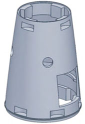
The 3D model of the aluminum alloy cabin product is shown in the figure. The overall dimensions are φ336.08 mm×455mm, with a minimum wall thickness of 2mm and a maximum wall thickness of 37mm. The overall structure is a revolving body, with four φ45mm circular windows in the middle of the product, one large and one small square window. The product design mass is 12.07kg, with thick walls at the upper, middle, and lower positions, and thin walls at other positions. This structure can lead to segmented solidification during the casting solidification stage, which cannot be solidified sequentially. The thick and large hot spot areas cannot be fully supplied, which can easily cause casting defects such as shrinkage and shrinkage holes. Therefore, the design of the product’s pouring system needs to consider providing sufficient supply to the hot spot areas.
Gating system scheme for castings
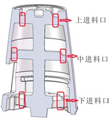
The low pressure casting pouring molding process is selected. The internal cavity of this product is a semi-closed structure, and the metal core cannot be demoulded, so the use of coated sand is adopted.The prototype is produced using a combination of sand cores and metal molds. After the product is deformed, the coated sand cores are removed to obtain the product blank. Based on a comprehensive analysis of the product structure and equipment characteristics, the product blank and pouring system are designed. According to the product size, the processing allowance of the product is designed, taking into account the shrinkage of thick parts of the product to ensure that the pouring process of the product achieves sequential solidification. The pouring system is designed as a stepped feed gate according to the product structure, with feed from three locations: top, middle, and bottom. The runner is designed inside the sand core, allowing aluminum liquid to pass through from inside the sand core while also providing thermal insulation for the aluminum liquid, as shown in the figure. After the pouring process design is completed, ProCAST casting simulation software is used to numerically simulate the melt flow field and solidification temperature field of the product blank. From the flow field analysis, it can be seen that after the melt enters the cavity from the gate, it fills rapidly from bottom to top, with stable filling of aluminum liquid without turbulence, and uniform overall flow velocity. From the temperature field, it can be seen that during the solidification stage, the center temperature of the casting is higher, with temperature decreasing gradually from the center to the outer wall, consistent with the casting solidification sequence. The pouring system can maximize heat sink shrinkage of the casting parts. The results show that using this pouring system for production results in stable fluid filling without splashing, and the temperature field meets the requirements of casting solidification sequence, ensuring that the hot spot parts of the product are fully shrunken without shrinkage defects such as porosity and shrinkage cavity, as shown in the figure.
Layout of demolding top rod
The product has a large volume and high quality, and how to smoothly remove the blank from the metal mold will directly affect the continuity of production. Therefore, the design of the ejector pin layout and draft angle of the product blank is extremely important. The metal mold of this product belongs to a four-open structure, which means that during the production process, the left and right cavities must be opened first, followed by the top and bottom cavities. The ejection process requires ensuring that after the top and bottom cavities are opened, the product blank remains in the upper mold cavity of the metal mold, and then is ejected through the ejector mechanism. Therefore, it is necessary to set a reasonable draft angle for the metal mold to ensure that after the top cavity is opened, the product blank and sand core can be brought into the upper cavity without falling off, and then the product blank can be smoothly removed from the upper cavity. Based on an analysis of the quality of the product blank and sand core, it is necessary for the upper mold cavity to have sufficient clamping force to bring the blank and sand core out of the lower mold cavity and leave them in the upper mold cavity. The lower mold cavity needs to minimize the clamping force to reduce the upward resistance during mold opening, so as to ensure normal mold opening and stripping. Based on previous mold testing experience, if the draft angle is set to 0, it will result in too much clamping force and the blank cannot be smoothly ejected. Therefore, a necessary draft angle needs to be given to the upper mold cavity within a certain range. Therefore, the draft angle of the upper mold cavity is set to 0.5° with a draft depth of 61.37mm; in order to reduce the clamping force of the lower mold cavity and minimize the machining allowance, the draft angle of the lower mold cavity is set to 5° with a draft depth of 56.84mm. As shown in Figure 5, after the product blank is opened in the upper mold cavity, it remains
Place the upper mold cavity, and then separate the product blank from the upper mold cavity through the ejector mechanism to achieve smooth material removal.
Casting defects and solutions
Local porosity in the casting
The 100% X-ray inspection of the aluminum alloy cabin showed that there was a certain degree of shrinkage porosity in the part shown in Figure 6. The analysis showed that this part was located in the middle of the product, with a wall thickness thicker than the upper and lower parts, belonging to the hot spot of the product. Due to the diameter of φ297.31mm, the wall thickness was relatively thick, which made it difficult to detect the porosity.The thickness is 24.24mm, and the upper and lower wall thicknesses are both 14.27mm, with a large difference in size. According to the principle of sequential solidification, by setting up riser and other process measures in the thick and large parts of the casting where shrinkage porosity may occur, the casting body can be solidified before the riser part, achieving local shrinkage compensation effect. During the numerical simulation design process, a ‘I’ shaped runner was designed in the middle of the part to act as a riser to provide shrinkage compensation. However, during actual production, it was found that due to the large diameter of the waist of the product, there was a local shrinkage problem away from the symmetrical position of the ‘I’ shaped runner’s internal gate.
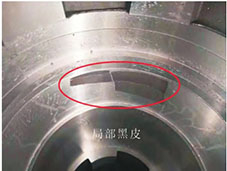
Local black skin appears on the inner wall of the casting after processing
After heat treatment of the casting, the casting blank was processed, and it was found that local black skin appeared on the inner wall of the casting after processing, that is, the part that could not be processed to see light.Moreover, the position is not fixed, indicating that the inner diameter of the product at the black skin is too large, and some of the blank dimensions cannot meet the processing requirements of the drawing, as shown in the figure.
Foundry solutions
The solutions to the problems found in the X-ray inspection results and processing of the castings are as follows: ① For local shrinkage, the “straight” runner is changed to a “cross” runner to enhance the feeding of the pouring system to the ring-shaped hot spot of the product, solving the shrinkage defects caused by insufficient feeding in this area. ② For the black skin phenomenon of different sizes on the inner wall of the casting during processing, the main reason is analyzed to be due to the drum cracking of the sand core during molding, and the local sand core protruding outward causing the inner wall of the casting to lack meat. The thermal expansion coefficients of the metal mold and the sand core are quite different, resulting in changes in the fit clearance between the metal mold and the sand core after heating. In order to solve this problem, a caliper is used to measure the high temperature of the cavity under the heating state of the metal mold, and compared with the measured size of the sand core.It was found that the size of the sand core area after heating the mold was smaller than the height of the sand core, causing cracks in the sand core during mold clamping. Therefore, the size of the upper cavity of the metal mold was reduced by 1mm, and the clamping gap between the upper and lower molds was increased to ensure that the metal mold would not crack the sand core during mold clamping. Production verification showed that changing the “straight” runner to a “cross” runner in the waist ring-shaped hot spot area of the product could effectively compensate for the volume shrinkage during solidification of the waist ring-shaped hot spot, solve the shrinkage deficiency of the waist hot spot, and ensure that the internal quality of the product meets requirements. At the same time, increasing the fit clearance between the metal mold and the sand core under thermal conditions can compensate for the interference fit caused by different shrinkage ratios between the metal mold and the sand core under thermal conditions, solving the problem of excessive deviation in the internal wall size of the product caused by cracks in the sand core during mold clamping of the metal mold.
conclusion
(1) According to the structural characteristics of the product, the draft angle of the upper mold cavity is set to 0.5°, the draft depth is 61.37 mm, and the draft angle of the lower mold cavity is set to 0.5°.The draft angle is 5°, and the draft depth is 56.84mm. During mold opening, it can ensure that the blank and sand core are brought to the upper mold and smoothly released through the material-removing mechanism, ensuring Maintain continuous production.
(2) In the low-pressure casting process of aluminum alloy cabin, when the temperature of the aluminum liquid is 700 ℃, the mold temperature is 320 ℃, and the filling and pressurizing speed is set to 0.0008 MPa·s-1, the aluminum liquid filling is the most stable.
(3) Conducting dimensional measurements while the metal mold is hot can truly reflect the fit clearance between the mold and the sand core, avoiding mold thermal deformation during production.The inner wall size of the product exceeds the tolerance due to expansion and sand core cracking.