
1. Preface
The crankshaft induction hardening process mainly involves adding parts through induction heatingHeat the crankshaft to 800-900 ℃ using a hot method, and then keep it warm for one minuteFor a period of time, about 10 seconds, and then spray the quenching liquid to make it fastThe process of rapid cooling. The induction hardening process can significantly improve the rigidity, hardness, wear resistance, fatigue strength, and toughness of parts.However, various quality issues can easily occur during induction quenching,Induction hardening cracks are a common problem among them. Induction quenching workerOther factors beyond craftsmanship, such as casting defects and inclusions in raw materialsThe quality of materials and machining can also have a significant impact on the occurrence of cracks during the heat treatment process. This article focuses on the study and discussion of induction hardening process itselfThe cause of fire cracks.
2 The Mechanism of Induction Quenching Cracks on Crankshafts
Figures 1 and 2 show a certain member of Shanghai Volkswagen Powertrain Co., LtdInduction hardening crack morphology generated during the production of crankshaft machining lines.The induction hardening crack occurred on the crankshaft of the casting, and the raw material is a ballDuctile iron TL124, with induction hardening cracks occurring at the main journalOn side IV, this quenching crack belongs to an occasional phenomenon. Supervision of daily productionThe control method is to continuously inspect and measure 5 pieces every hour, and induction quenching is found during the inspectionAfter the fire cracks, 100% non-destructive testing will be conducted to determine the proportion of cracks that occurAround 3%.

Figure 1 Quenching Crack 1 on the Side of the Crankshaft Journal

Figure 2 Quenching Cracks on the Side of the Crankshaft Journal 2
The mechanism of quenching cracks: the crankshaft has been cooled by quenching sprayDuring the process, both thermal stress and tissue stress were generated. Due to temperatureThe reduction creates thermal stress inside the crankshaft. Material expands according to its thermal expansionRegularly, shrinkage occurs during cooling, while the cooling rate of adjacent parts decreasesDifferent, resulting in differences in specific volume at any time during the cooling process,Mutual stress is called thermal stress. Thermal stress is often compressive stress.The tissue stress is the process of tissue transformation as the temperature decreasesDuring the transformation from austenite to martensite, the specific volume of martensite is greater thanAustenite, during martensitic transformation, is accompanied by an increase in the amount of martensiteThe component expands and the adjacent parts of the component cool to the martensitic transformation point MsThe time of the onset temperature of martensitic transformation is different, thus causing internalOrganizational stress is generated in the department. The structural stress is caused by surface quenching of the crankshaftTensile stress. Above Ms, only thermal stress mechanism exists, below MsBoth mechanisms occur simultaneously, but linear expansion caused by martensitic transformationThe expansion is greater than the thermal expansion, so the stress mechanism of the structure below the Ms point is dominantTo be effective. Internal stress refers to the difference between tissue stress and thermal stress.When the internal stress is lower than the yield limit, the part undergoes elastic deformation.When the internal stress exceeds the yield limit, the part willThere is a risk of cracking when local plastic deformation occurs. DangneiThe stress is greater than the material yield limit, resulting in plastic deformation. Internal stress maintenanceAfter continuous increase, the parts undergo brittle fracture, ultimately leading to the occurrence of cracksHealth. Induction hardening of crankshafts is often observed through a microscope in the laboratoryAfter analyzing the fracture morphology and appearance status of cracks, it can be concluded that quenching cracks areBrittle fracture under internal stress.
3 Analysis of the Causes of Induction Hardening Cracks on the Crankshaft
The induction hardening process mainly heats the parts to a critical temperatureTemperatures above Ac3 (hypoeutectoid) or Ac1 (hypereutectoid), i.e. between 800 andHold at 900 ℃ for a period of time to fully or partially austenitize, andAfterwards, rapidly cool to Ms at a rate greater than the critical cooling rate (martensitic transformation initiationMartensitic transformation occurs below temperature.Internal cause: The essence of martensite is the internal cause of quenching cracks, while MaThe crystal structure, chemical composition, and casting defects of martensite are the basis of martensiteThe influencing factors of material brittleness.External factors: caused by various process conditions and part sizes and shapesThe magnitude, direction, and distribution of macroscopic internal stress are related to quenching cracksExternal factors.Due to the complex shape of the crankshaft, the reasons for the cracks areMultiple, requiring macroscopic observation, chemical composition analysis, and metallographic examinationMeasurement, mechanical performance testing, fracture morphology analysis, structural design, and mechanical testingAfter comprehensive analysis of processing quality, heat treatment process, and casting defects,Only then can we draw a definite conclusion. Possible causes of quenching cracksAnalyze as follows.
(1) The increase of carbon content in raw materials and alloy elementsAdding will reduce the fracture strength of martensite. Effect of alloying elements on quenching crackingThe influence of patterns varies .(2) The original state before quenching is opposite to the original state before quenchingThe influence of quenching cracks is also significant, such as flake pearlite; horseNon equilibrium structures such as martensite and bainite; Uneven network of carbides;Non metallic inclusions; The thermal structure and flow lines during casting may cause and promote quenching cracks. In addition, shrinkage, slag inclusion, and severe rollingManufacturing defects can cause significant unevenness in the material.(3) The size and appearance of the parts are related to the cracking of the workpiece after quenchingThe shape is closely related, and it directly affects the quenching stressSize and distribution. Often there are gaps, sharp corners, grooves, and voids on the workpieceThe sharp changes in the cavity and cross-section are the concentration points of internal stress during quenching, which are cracksHigh risk areas where wrinkles occur. The parts in the red box in Figure 3 are allThe stress concentration of the crankshaft in this series model.
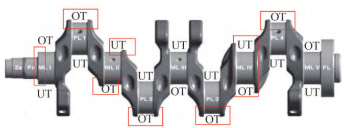
Figure 3 Quenching stress concentration on crankshaft parts
(4) Improper heating during heat treatment: Heating temperature and insulation of workpiecesTime can become the trigger for quenching cracks. The heating temperature increases during quenchingThe higher the temperature, the greater the tendency for quenching and cracking. If the quenching temperature increases and the heating insulation is carried outProlonged time leads to the growth of austenite grains, resulting in coarse quenched martensiteThe root with an increased tendency for quenching and cracking is characterized by a decrease in fracture strength and embrittlementThis reason.(5) When the cooling speed of the quenching liquid is too fast, it may causeThe rapid transformation rate of martensite results in significant structural stress, resulting inThe workpiece deforms or even cracks, resulting in cooling during martensitic transformationThe speed should be slower.The concentration of quenching solution has a direct impact on the cooling rate: concentrationInversely proportional to the cooling rate, the cooling rate decreases as the concentration increases; backWhen the concentration decreases, the cooling rate increases. Reducing the concentration of quenching solution canBy adding tap water and increasing the concentration of quenching solution, the original solution can be added. quenchingThe effect of liquid temperature on cooling rate: temperature is inversely proportional to cooling rateThe higher the temperature, the lower the cooling rate. Conversely, the lower the temperature, the coolerBut the higher the speed.The quenching crack position generated by a certain crankshaft production line is fixed, and 2The occurrence of secondary quenching cracks occurs in the later stage of quenching liquid use,The quenching solution has been in use for about 2 months. After replacing with a new quenching solution, noQuenching cracks present. Therefore, quenching cracks were generated on a certain crankshaft production lineThe main reason is locked in the actual concentration decrease and cooling rate increase of the quenching liquid in the later stage of use.
4 Monitoring method for quenching solution concentration
Currently, there are two commonly used methods for monitoring the concentration of quenching solutionTypes: refractive method and viscosity method.Due to the simple and convenient operation of the refractive method, it is widely used in the production lineWidely used. The production line can be straightened using a handheld refractometer (see Figure 4)Obtain the quenching concentration.
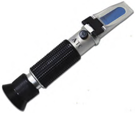
Figure 4 Handheld refractometer
4.1 Operation steps of refractive method
(1) First step zero calibration: Before each concentration measurement,The refractometer needs to be zeroed. Drop tap water on the mirror surface of the refractometerClose the cover and observe the light dark boundary in the field of view, and adjust theZero screw to make the line coincide with the zero mark on the right side, then use clean soft paperThoroughly wipe and absorb any moisture from the lens and cover.(2) Step 2: Measure the concentration of the quenching liquid: Measure the quenching liquid to be testedDrop on the mirror surface, close the cover, and read the right side of the light dark boundary in the sceneThe scale value on the side, multiplied by the fixed refractive index of the quenching liquid of 1.9, isKnow the concentration of the measured quenching solution.
4.2 Operating steps of viscosity method
(1) Step 1: Sample installation: The inner diameter meets the requirements and is cleanLoad the sample into a dry capillary viscometer; When installing the sample, apply the rubberCover the small glass branch of the thick tube and block it with your index fingerTurn the viscometer upside down and insert a long glass tube with a capillary tube into itWithin the sample, use ear balls to suck the sample through a rubber tube to the second notchDegrees (make the liquid level tangent to the scale), then place it upright and wipe off the viscosityMeasure the external sample and remove the rubber tube from the bracket to cover it with capillariesThe long glass mouth of the tube.(2) Step 2: Constant temperature: Immerse the viscometer containing the sample inPrepare a pre prepared constant temperature bath (see Figure 5) and fix the viscometer on the bracket with a clamp, adjusting the viscometer to a vertical position. tryMaintain a constant temperature of ± 0.1 ℃ and a constant temperature sample for about 15 minutes.(3) Step 3 measurement: Suck the sample onto the glass ball on topRecord the outflow time of the sample from the first to second scale, and weighRepeat until the difference in seconds between the two measurements does not exceed 0.2%,Take the average of two times.
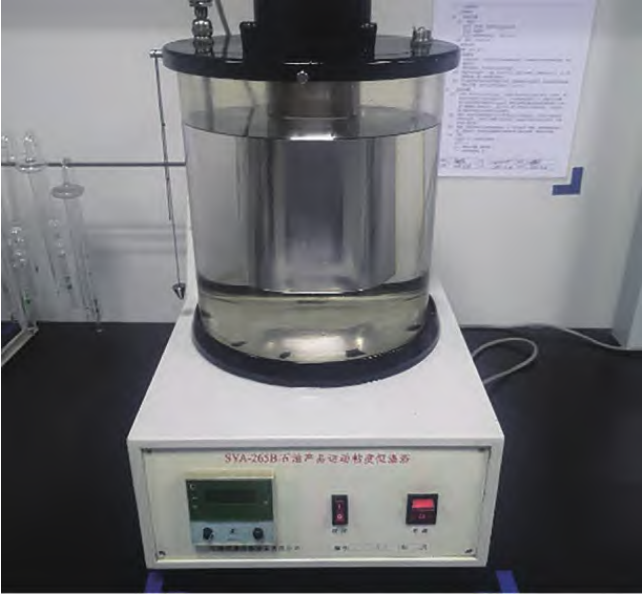
Figure 5 Constant temperature bath
In the later stage of quenching liquid use, the actual value calculated by viscosity methodThe actual situation where the concentration is closer to that of the quenching solution is becauseDissolving substances in the influent water can change the refractive index of the aqueous solutionThe contribution of mass to the refractive index of a solution is proportional to its concentration in the solutionThe total refractive index of the solution is the contribution of each solute to the refractive index of the solutionThe simple stacking value of Xian. According to this pattern, measured with a refractometerIt will be the total refractive index of all solutes in the solution. Due to the use of quenching fluidIt is inevitable to be contaminated afterwards, so soluble pollutants will also increase the solutionThe refractive index of. In this way, the refractive index of the quenching solution after use is determined byCompounds, additives, self pollution of water, and external pollutantsThe contribution to refractive index is added together. The longer the quenching liquid is used, the moreThe longer the quenching amount, the more severe the pollution, and the required refractometer concentrationThe higher it gets. Do not understand this reason, continue to quench according to the new formulationWhen the refractive index reading of the liquid is used to control the concentration of the quenching solution, it will causeQuenching caused by low concentration of PAG polymer and fast cooling rateCracking.In fact, it is also true that the production line has found that when quenching liquid is usedAfter a period of time, due to a certain degree of pollution, a refractometer was usedThe measured concentration may deviate from the actual concentration and often be higher than the actual concentrationAt this point, the kinematic viscosity and cooling characteristic curve of the quenching liquid should be usedCheck the “refractive index” of the quenching solution using a line.
Therefore, in actual production, as the use time of quenching solution increasesPlus, it is necessary to calibrate the concentration of the quenching solution and correct the refractive index, rather thanThe refractive index of the new liquid is fixed at 1.9. Currently, a certain crankshaft productionThe actual monitoring method of the production line is: the laboratory regularly takes samples from the production line every weekSample, concentration A measured by the kinematic viscosity method, and concentration A measured by the refractive index methodRefractive reading B, refractive index of quenching solution C=concentration (viscosity) A/foldLight reading B. The updated refractive index C is then fed back to the production line usingCalculate the latest concentration value of quenching solution on a daily basis on the production line. Production line connectionBy using this method, the refractive index of the quenching solution during its service cycle is monitored weeklyThe changes have formed a certain amount of big data statistics, as shown in Table 2. withAt that time, the production line tracked 6 quenching attempts at different number of processed workpieces on siteThe change trend of liquid refractive index provides timely detection of refractive index in productionProvide a basis for troubleshooting data anomalies. Refractive Coefficient of Quenching Solution and Quenched WorkpiecesThe relationship between quantities is shown in Figure 7.
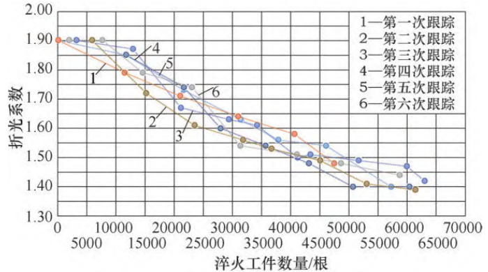
Figure 7 Relationship between the refractive index of quenching solution and the number of quenched workpieces
5. Pollution of Quenching Solution and Preventive Measures
From Figure 7, it can be seen that as the number of quenched parts increases, the quenching solutionThe refractive index of also gradually decreases, indicating that the quenching solution has been contaminated,The decreasing slope also reflects the speed at which the quenching solution is contaminated. becauseTherefore, the production line should pay more attention to the contamination of quenching liquid in daily processingSituation.The pollution of common quenching fluids can be divided into oil pollution and non solid pollutionThere are three major categories of particulate pollution and water-soluble pollution, which should be determined according to the situation in productionHandle the situation accordingly.(1) Under normal circumstances, a small amount of oil contamination floating on the liquid surface does not affect the cooling characteristics of the quenching solution, but can be anaerobicThe reproduction of bacteria creates conditions that can easily make the quenching solution stink, as long as it is frequently usedSuck off the oil stains with a clean newspaper. If the quenching solution is mixedSoluble oils can seriously affect the cooling characteristics of the quenching solutionCracking of the workpiece.(2) Insoluble solid particles mainly come from the quenching of workpiecesThe oxide skin introduced has little effect on the cooling characteristics of the quenching solution, butRegular filtration and slag removal should be carried out during production. Suspended solid particles oftenIncrease the refractive index of the quenching solution, therefore the quenching solution should be measured after filtrationThe refractive index of.(3) Soluble contamination can change the color and refractive index of the quenching solutionThe rate has varying degrees of influence on the cooling characteristics of the quenching solution (someSoluble substances can alter the formation characteristics of PAG polymer films, thereforeTry to avoid it as much as possible. If subjected to such pollution, heating and purification can be usedMethod: Utilize the reverse solubility of PAG to restore the positive state of the contaminated solutionChang. Therefore, the workpiece must undergo pre cleaning before entering the quenching station,Pay attention to the physical quality of parts by detecting their cleanliness.
6 Conclusion
This article analyzes the various factors that affect the quenching cracks of the crankshaftPlain, including blank, previous rough machining, quenching parameters, and quenching solution concentrationStarting from the principle, the occurrence of quenching cracks in the crankshaft was analyzed based on factors such as temperaturePossible reasons for this. The production line mainly found quenching through research and analysisThe decrease in actual concentration during the later use of the fire liquid seriously affects the quenching of the crankshaftThe reason for the occurrence of fire cracks has changed the concentration monitoring of the quenching solutionMethod: Update the refractive index using the viscosity method and simultaneously focus on quenchingThe contamination of the fire liquid effectively solves the problem of crankshaft quenching cracksThe question also accumulates for solving other quality problems such as crankshaft heat treatment in the futureHaving gained experience and laid the foundation.