
The oil pan is the lower half of the crankcase, also known as the lower crankshaftA box is used to store engine oil. When the engine stops runningWait, a portion of the oil inside the engine will be affected by gravityReturn to the oil pan; After the engine starts, the oil pump controls the engineOil is carried to various lubricating components of the engine, with most of the oilUsually in the oil pan; It is a closed crankcase that serves as an oil storage tankThe outer shell of the diesel engine prevents impurities from entering and collects and stores lubricating oil flowing back from various friction surfaces, dissipating some heat,Prevent oxidation of lubricating oil.The material of the oil pan casting is HT250, and the wall thickness of the casting is (6~30) mm, with an overall dimension of (601.5 × thirty-two × 163) mm, structuralThe shape is shown in Figure 1. Requires a machining allowance of 3 mm for the installation surface, includingThe machining allowance for the installation surface of the connecting plate is 2.5 mm, and the machining allowance for the tower surface is 2.5 mmMm, as shown in Figure 2.
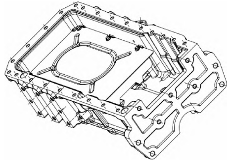
Fig. 1 Structure and form of oil pan
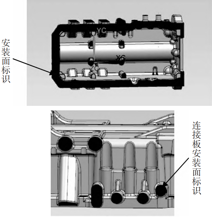
Fig. 2 Marking of machining surface
The oil pan is usually cast using sand mold technology, but due to production costsFactors such as high and significant environmental pollution are gradually being replaced by lost foam casting.Lost foam casting is a type of precision casting with small machining allowance that has emerged in recent yearsThe formed casting process simplifies the production process and shortens the process flowCheng has improved production efficiency and reduced labor intensity, with significant advantagesAnd it is easy to see, so the company uses lost foam casting for the production of oil panArt. Based on an oil pan produced by the company, this article focuses on theExploring and practicing the bottom shell lost foam casting technology.
1 Industrial Test Plan
1.1 Process difficulties
The oil pan belongs to small to medium-sized thin-walled shell components, which are cast and shapedPoor shape and size, prone to deformation, inconsistent mouth width, etcDefects in the four key areas of model, coating, modeling, and process methodsThe selection of technical points [2] determines the casting process based on comprehensive considerationsForming performance and stability of shape and size. Combined with structural dimensionsThe main casting defects are slag inclusion, sand sticking, cold shuts, etc.
1.2 Design of Lost Foam Casting Process
1) The process principle is the lost foam casting process, which uses dualDesign and layout of circulation separation line, mainly including casting mold making workersSequence, casting model bonding and coating process, casting sand treatment, castingThe cleaning, electric furnace melting process, and machining process are composed of four parts.This article focuses on the mold production and casting process;2) White mold production uses H-S beads, with a density controlled at(22-26) g/L, heated on a molding machine at (40-50) ℃ for 3Ensure that the model is fully matured, and perform necessary tests on the white mold before drying itRequired correction processing; Due to the tendency of thin-walled parts to deform during the pouring process,Fiber rods and coated sand pads need to be used for support and shapingCard board, adhesive shape and size as shown in Figure 3, using cold glue and hot glueThe coordinated use of glue ensures the uniformity of processing allowance;
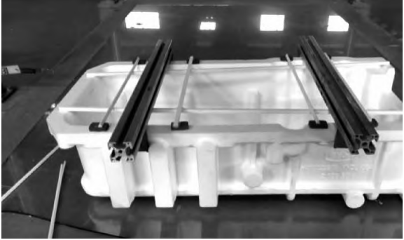
Fig. 3 Bonding shape requirement
3) Closed gating system is used for thin-walled parts, and foam is used for largePlate cutting and cutting, and the structural dimensions of the pouring system are shown in Figure 4Using a top pouring system with a hollow sprue, water is fed at two points,As shown in Figure 4;
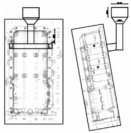
Fig. 4 Casting system arrangement
4) Use a specialized water-based coating for lost foam molding, with a uniform coating layerNo leakage, stacking or other phenomena [3], manually adjust the model (riser, pouring)The entire system (casting) is placed in the container, using penetration coating and brushingBy combining the methods, the position where the coating can be penetrated allows the model to naturally soak the coating, while the area where it cannot be penetrated is brushed to ensure that the coatingCover the entire model with material, and use fiber cloth to wrap and thicken the riserMaterial; Hang the model with paint, and change the positions for the first, second, and third coatsSet up baking and make shaping brackets to prevent baking deformation;5) Using (0.4-0.8) mm molding sand, 6 pieces per boxThe principle of buried box modeling is followed. The placement of the yellow mold is shown in Figure 5.Firstly, fix the model with the bottom sand, and clamp the sand box tightly after the model is fixedThe shaking table first undergoes bottom shaking, and then adds sand while shaking, with molding sand addedStop adding sand and vibrate tightly when reaching the three tie bar positions before continuing to add sandStop adding sand when the molding sand covers the top of the oil pan by about 80 mm,The total vibration time shall not be less than 360 seconds, and the vibration frequency shall be (40-45) Hz;
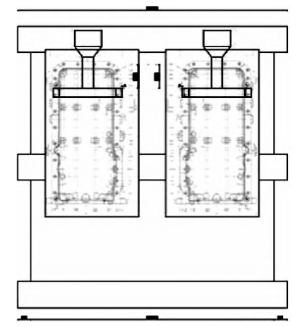
Fig. 5 Yellow mold locating place
6) The feeding sequence for smelting is first scrap, then return to the furnace, and finallyFerrosilicon, manganese iron is added before furnace discharge, and carburizing agent is added during the process to increaseThe carbon agent uses a low sulfur carburetor, and after all the furnace materials are put into liquid form,Add a covering agent (slag remover) to protect the molten iron from melting and preventPrevent oxidation of molten iron. Sampling after the temperature of molten iron in the furnace reaches the sampling temperatureAnalyze chemical composition and conduct pre furnace analysis.
7) The temperature of molten iron is (1520 ± 20) ℃, and the pouring temperature isControlled at (1 380 ± 20) ℃, the molten iron must pass theAllow for (2-3) minutes to settle, carry out inoculation treatment, and discharge the slag again.Control the single casting time within 30 seconds, control the single box casting time within 3 minutes, and maintain the pressure for 3 minutes after pouring;8) The sprue and riser are cut using diamond cutting blades, usingQ3716 hook type shot blasting cleaning machine for shot blasting treatment, single shotThrow 4 pieces, based on the surface being smooth and free of debris.
2 Existing problems
During the production test process, the casting undergoes deformation (with no machining allowance)Surface quality defects such as slag inclusion, sand sticking, and cold shuts, resulting in internal defectsInternal defects such as shrinkage, porosity, and substandard metallographic structure are severeThe qualification rate of casting products is affected, as shown in Figure 6.
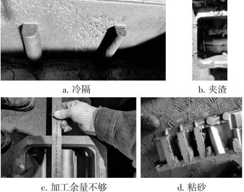
Fig. 6 Casting defects
Using the lost foam casting process to produce shell castings, regardless ofIs it white mold production for producing foam and runner design, or smeltingThe molding, pouring, and lost foam casting process have a significant impact on the quality of each process linkThe requirements for quantity control are quite strict, and the production of qualified castings must go throughOnly through the tacit cooperation of multiple processes and operators can it be achieved. So,The occurrence of casting defects gradually accumulates throughout the entire process flowThe ultimate result of accumulation, amplification, and extension is the scrapping of the casting.
3 Analysis of Defects in Oil Pan Lost Foam Casting
3.1 Analysis of causes of deformation defects
The oil pan belongs to the thin-walled shell type casting, with a large inner cavity and thin walls,In the process of lost foam casting, deformation is prone to occur, mainly concentratedAt the wide edges on both sides, as shown by the letter a in Figure 7. In trial productionDuring the process, the scrap rate caused by excessive deformation is as high as 50%.
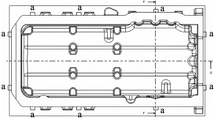
Fig. 7 Position prone to deformation
Following the test process, the main reason for deformation is that the foam modelDuring the processes of forming, drying, assembly, coating, and vibration burying the boxCaused by unreasonable operating methods or lax control; In addition, vibration compactionWhen burying the box, the pressure exerted by the molding sand on the model in different directionsDifferent, it can also cause deformation of the casting. Therefore, for the model, it is important toOperation control during drying, placement form during drying, and coating applicationThe method and operation of burying box modeling must have strict operating standards andControl measures requirements.
3.2 Analysis of causes of sand sticking defects
Uneven distribution of reinforcing connecting ribs in the oil pan and particles in the molding sandUneven and high ash content make it difficult for molding sand to flow into corners during the molding processThe negative pressure and compaction effect of the area are poor, and the compactness of the molding sand is reduced.In addition, the thickness and strength of the coating are not sufficient, resulting in the impact of high-temperature and high-pressure molten ironUnder the action of brushing, it is easy to break through the coating and produce sand sticking defects. Clay deficiencyThe sunk casting is shown in Figure 8.
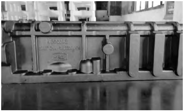
Fig. 8 Metal penetration defects
3.3 Analysis of the causes of slag inclusion defects
The casting process is poor, and molten iron infiltrates the model during the casting processMedium or impact molding sand, mixing washed away paint or molding sand with metalIn the liquid, slag inclusion defects are formed after the casting solidifies; Slagging, blockingThe slag removal process is poor, and the model generates a large number of solid products and liquidsPhase products, when solid and liquid products cannot be discharged in a timely mannerWhen it remains inside the casting, it forms slag inclusion defects .
3.4 Analysis of the causes of cold shuts, shrinkage and porosity defects
The flow velocity ratio of molten iron during pouring for thin-walled shell castingsThick and large castings have slow flow times and a faster rate of temperature reduction,At the final destination of the molten iron, due to excessive heat consumption, it is not possible toCompletely fused to form a cold barrier; The pouring system is unreasonable, making it necessaryWhen there is no time to replenish enough molten iron in the contracted area, the interior is alreadySolidification causes shrinkage and porosity, as shown in Figure 9.
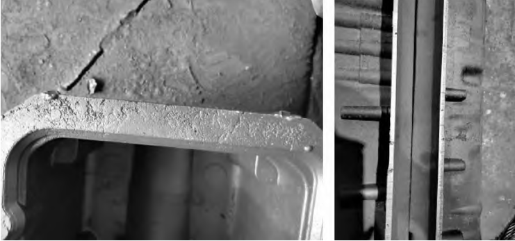
Fig. 9 Cold shut, shrinkage porosity defects
3.5 Analysis of Reasons for Failure to Meet Metallographic Structure Standards
The on-site ingredients were not strictly weighed and added, and the raw material ratio was not controlled properlyStrict, unstable chemical composition; Poor inoculation effect, carbon equivalentLow, Si/C does not meet the requirements, with Si/C ranging from 0.6 to 0.7 being the best. NoThe qualified metallographic structure is shown in Figure 10. As shown in Figure 10The proportion of black spots is less than 10%, and the content of pearlite is not up to standard.
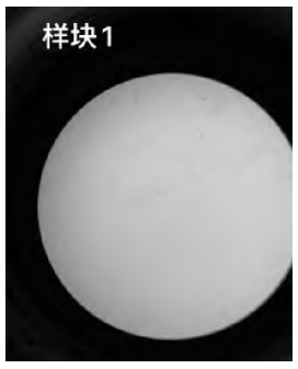
Fig. 10 Unqualified metallographic structure
4 Improvement Measures for Defects in Oil Pan Lost Foam Casting
Analyze the causes of deformation, slag inclusion, sand sticking, cold shut, shrinkage porosity and shrinkage defects in the oil pan casting, and improve them through process experimentsImprove and optimize production processes and processes, and implement accordinglyAdhere to standards, carefully control and supervise, improve process yield and productionProduct qualification rate.
4.1 Improvement measures for deformation defects
The white mold drying process is laid flat, with multiple points of stress, and can be used after dryingThe hygrometer measures humidity and can proceed to the next process once it meets the requirements;Use a fixed card to set the size, and then use a fiber rod for bondingThe bonding method of the rod is shown in Figure 11, and the dimensions are measured again after bondingPaint after meeting the requirements. Ensure one coat of Baume degree and coating thickness, adjustThe entire drying process parameters are suitable for low drying starting temperatureWhen extending the drying time to ensure contraction balance, the parameters are shown in Table 4.
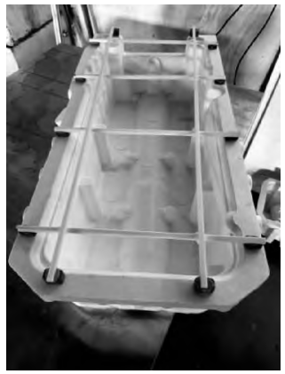
Fig. 11 Fiber sticks bonding way
When burying the box for molding, the bottom sand is manually spread and evenly added during the sand adding processSand, evenly stressed, making buried box shape positioning device to ensure burialBox angle, misplaced box embedding, layered sand addition, layered compaction, cornerArtificial sand construction at the location has greatly reduced the cost by adopting the above measuresThe generation of class defects [7], in order to prevent casting deformation caused by deformationReduce the scrap rate to within 3%.
4.2 Improvement measures for sand sticking defects
1) The coating can firmly adhere to the white mold. The coating is dense andSufficient strength to ensure no detachment during operationPhenomenon: No cracking during vibration of sand filling molding [4]. Add to the coating3% bentonite, 15% graphite powder, 15% ratioQuartz powder enhances strength and flowability, with a uniform coating thickness that is not lowAt 1.6 mm;2) When styling, the strength should not be too strong to prevent coating during stylingDamaged, vibration time should not be too long, and the coating is prone to cracking.The test confirms that the total seismic time at a frequency of 40 Hz is not less than 360 seconds,The total seismic time is 280 seconds at a frequency of 50 Hz. At the same time, it is necessary to takeThe auxiliary means are to manually fill and compact the molding sand with sand at the corner position,Ensure that the molding sand at the dead corners has high compactness;3) The selection of molding sand for modeling must be suitable. For dry sand moldingThe sand must be of the specified mesh size and in a circular or approximately circular shapeIt’s quite ideal. For general cast iron and ordinary steel castings (0.4~Use a screening machine to screen the used molding sand for 0.8) mm of sandScreen out larger and smaller particles of molding sand and internal dust, andReplace with new sand;4) Select the appropriate negative pressure and the negative pressure used during pouringExcessive pressure can easily cause severe sand sticking, and casting collapse due to low negative pressure. castingThe negative pressure of iron should be controlled within (0.04-0.05) MPa. Misalignment during box embeddingBox to avoid overlapping surfaces of castings affecting negative pressure distribution;5) Select suitable pouring temperature and implement pouring temperature on siteIt should not be too high. The higher the temperature, the stronger the penetration force of the metal liquid, and the easier it is to penetrateSand sticking, pouring temperature controlled at (1420-1460) ℃, single packPour one box, do not pour multiple boxes.
4.3 Improvement measures for slag inclusion defects
Regular blowing of the furnace floor, furnace surface, and surrounding furnace body; Timely furnace nozzleRepair; Frequent slag tapping, slag tapping in the furnace is carried out in four steps, with two steps in the furnaceUnder high power state, slag is removed by standing at the two-step furnace mouth, and the furnace nozzleRepair and clean the nozzle in a timely manner, apply repair materials, and clean the bag before leaving the water;Static slag tapping inside the bag, divided into three steps: ① Pour the molten iron into the bag for operationOne slag tapping; ② Cover the slag remover to transport the molten iron ladle to the pouring areaLet it stand and make another slag; ③ During pouring, the slag agent is used to cover and only one flow port is reserved. The position of the flow port is blocked by a fiber blanket, and at the same timeAdd exhaust and slag discharge ports on the upper processing surface.
4.4 Improvement measures for cold shuts, shrinkage and porosity defects
Increase the tapping temperature, pouring temperature, and pouring of molten ironSpeed, increase the outlet temperature to 1 540 ℃ (increase to1 560 ℃), using a rapid pouring method. gating system The design is the key process of lost foam casting, and the calculation determines the pouring processThe cross-sectional area of each component in the system is improved through process experimentsOptimize to make it reasonable [8]. Optimize the shape of the sprue and use a cylindrical shapeVertical pouring channel, top pouring inclined pouring process, selected according to design principlesDetermine the cross-sectional size of the pouring system, and the proportion of the pouring system cross-sectional area shall be in accordance with the straight lineGate: Horizontal gate: Inner gate 7:1:0.4 control. Adopting middle annotationThe pouring system is divided into two points for water inflow, which not only blocks slag but also ensuresSupplement amount, as shown in Figure 12. Follow the “slow fast slow” pouring principleThen, first slowly open the channel, with an estimated pouring time of 2 seconds, and thenRapid pouring, with an estimated pouring time of 20 seconds, and finally reaching the position of the transverse runnerSlowly pour until fully poured, estimated time of 3 seconds, total single pourThe injection time shall not exceed 25 seconds. Set up supplementary and concealed pipes at the concentrated position of the cold shut offMouth, as shown in Figure 13.
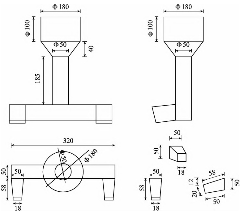
Fig. 12 Casting system structure
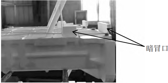
Fig. 13 Setting of cold shut blind riser
4.5 Improvement measures for substandard metallographic structure
Optimize the chemical composition of the oil pan, adjust the composition ratio, and control carbonEquivalent is between 3.8% and 4.1%, Si/C is controlled at around 0.65, and molding sandMoisture control is between 3.2% and 3.5% [9], and raw and auxiliary materials are strictly weighed in proportionAdd, increase the intensity of furnace composition inspection, and adjust the addition ratio in real-timeFor example, ensuring that the ingredients are qualified before being discharged, optimizing the process, and determining the respective componentsAddition time and temperature of gold element, carburizing agent at 1/4 molten iron and 1/2 ironWhen adding water to 3/4 of the molten iron, the single addition amount shall not exceed 40 kg, and 3/4 of the manganese ironWhen adding molten iron, add ferrosilicon 10 minutes before discharging to make the feeding materialThe device changes the inoculation inside the furnace to surface inoculation, improving the inoculation effect,Use insulation boards to improve the insulation effect of the pouring ladle, ensuring that the incubation time is not too longLess than 5 minutes, inoculants are added in proportion and according to requirements, and the inoculation processIt needs to be left to fully react.
5 Implementation effect
After the improvement of the above measures, formulate process standards and specifications, strictly followThe established process standards have been used to trial produce 6 batches of oil pans, with single batch trial production32 pieces are produced, and batch production tests have shown that using support ribs canTo prevent deformation of the appearance; Using a cylindrical sprue effectively solves the problemDefect of slag inclusion; Adjusting compaction parameters and manually assisted sand burial measuresSolved the iron clad sand defect; Increase the tapping temperature and pouring of molten ironInjecting temperature and using rapid pouring methods to eliminate defects in cold shutsThe problem has been effectively controlled, improving the pouring system and adjusting the compositionEffectively improve the internal defects and structure of castings through proportioning. Casting and processingAs shown in Figure 14, the casting yield can reach 96%.
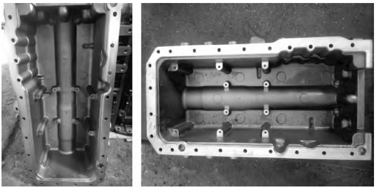
Fig. 14 Processing qualified castings
6 Conclusion
By analyzing the defects that occurred during the lost foam casting process of the oil panConduct a summary and analysis, and take practical, feasible, and effective measuresAnd track and improve, and obtain the following conclusions:1) Standardize the white mold baking method and buried box molding process, produce shaped card boards, and use fiber rods for fixed bonding to control casting deformation;2) The coating has good flowability, and a type of (0.4-0.8) mm is selectedSand, vibration frequency during molding ≥ 40 Hz, casting negative pressure ≥ 0.04MPa, pouring temperature controlled at (1420-1460) ℃, lack of sand adhesionImproved subsidence;3) Solidification slagging process and slag blocking method, using large particle slaggingSlag agent reduces surface slag inclusion defects. Set at the concentrated position of the cold partitionInstall a shrinkage blind riser, use a closed pouring system, and use a cylinderThe shaped sprue effectively controls the defects of cold shuts, shrinkage cavities, and porosity;4) Adjust the proportion of raw materials to determine the addition of alloy elementsControl the temperature between 0.6 and 0.7 Si/C to ensure the pearlite contentStable, with metallographic organization meeting standards.