This article focuses on the numerical simulation of the squeeze casting process using the Smoothed Particle Hydrodynamics – Finite Element Method (SPH – FEM) coupling approach. It elaborates on the model construction and simulation procedures, including the establishment of SPH and FEM mathematical models for the filling and solidification processes, respectively. The simulation program for the SPH – FEM coupling analysis method is independently developed. The flow and thermal stress fields during squeeze casting are numerically simulated, and the simulation results are validated through a case study of an extrusion casting bracket part. The SPH filling process simulation results are compared with those of commercial software, showing good agreement. The temperature and stress fields during the FEM solidification process are analyzed, revealing that the cooling rate and effective stress are highest at the thin walls on the side of the bracket part. The research demonstrates that the developed numerical simulation program based on SPH – FEM coupling provides accurate and reliable results, offering valuable insights for optimizing the squeeze casting process and predicting potential defects.
1. Introduction
Squeeze casting is a near-net shape forming technology that combines the characteristics of casting and forging processes. It is widely used in various industries due to its ability to produce castings with precise shapes, high surface quality, uniform microstructure, and fine grains. However, challenges such as gas entrapment and stress concentration can occur during the process, especially when forming thin-walled parts. Numerical simulation has emerged as a powerful tool to predict and address these issues, enabling process optimization and defect reduction. This article presents a comprehensive study on the numerical simulation of the squeeze casting process using the SPH – FEM coupling method.
1.1 Squeeze Casting Process and Its Significance
Squeeze casting offers several advantages over traditional casting methods. It allows for the production of high-quality components with enhanced mechanical properties and reduced machining requirements. The process involves the slow filling of the mold cavity with liquid metal followed by solidification under high pressure. This combination results in improved part integrity and performance. The ability to accurately predict and control the process parameters through numerical simulation is crucial for achieving consistent and reliable results in squeeze casting.
1.2 Numerical Simulation in Squeeze Casting
Previous studies have demonstrated the effectiveness of numerical simulation in understanding and optimizing the squeeze casting process. Various methods, such as the SPH and FEM, have been applied individually or in combination to analyze different aspects of the process, including fluid flow, heat transfer, and stress evolution. The SPH method is particularly suitable for simulating fluid flow with free surfaces, while the FEM is widely used for stress and strain analysis. By coupling these two methods, a more comprehensive and accurate simulation of the squeeze casting process can be achieved.
1.3 Objectives of This Study
The primary objective of this research is to develop a reliable numerical simulation program based on the SPH – FEM coupling method for the squeeze casting process. This involves establishing accurate mathematical models for both the filling and solidification stages, implementing an efficient coupling strategy, and validating the simulation results through experimental comparisons. The study also aims to analyze the flow, temperature, and stress fields during the process to gain a deeper understanding of the physical phenomena and identify potential areas for process improvement.
2. SPH – FEM Coupling Numerical Simulation Method
The SPH – FEM coupling method combines the strengths of the SPH and FEM to overcome the limitations of each individual method. The SPH is used to simulate the filling process, taking advantage of its ability to handle free surfaces and complex geometries. The FEM is then employed for the solidification process to accurately calculate the stress and strain fields. The coupling between the two methods is achieved through a carefully designed data transfer process.
2.1 SPH Mathematical Model for Filling Process
The SPH method approximates the physical fields using particles. The continuity, momentum, and energy equations are discretized in the SPH form to simulate the fluid flow during the filling process. To handle the complex fluid dynamics, artificial viscosity and stress terms are introduced to prevent particle penetration and instability. The boundary conditions are modeled using the virtual particle method, which enables accurate representation of the solid walls. The SPH model is formulated as follows:
2.1.1 Particle Approximation
The field function and its spatial derivatives are interpolated using the particle approximation method:
where is the central particle, is the neighboring particle, is the mass of particle , is the density, is the approximate function of particle , is the total number of neighboring particles, is the smoothing kernel function, and is the gradient operator.
2.1.2 Continuity, Momentum, and Energy Equations
The continuity, momentum, and energy equations in the SPH form are given by:
where is the velocity, is the internal energy, is the pressure, and and are the coordinate directions.
2.1.3 Artificial Viscosity and Stress Terms
To handle the complex fluid dynamics, artificial viscosity and stress terms are introduced:
where is the artificial viscosity term, is a coefficient, is the average sound speed, is the artificial viscosity coefficient, and is the average density. The artificial stress term is given by:
where is the artificial stress term and is a coefficient.
2.1.4 Boundary Conditions
The boundary conditions are modeled using the virtual particle method. Virtual particles are placed outside the solid walls to interact with the fluid particles and enforce the boundary conditions. The interaction between the virtual and fluid particles is modeled using the fluid dynamics equations.
2.2 FEM Mathematical Model for Solidification Process
After the filling process is completed using the SPH method, the temperature field results are transferred to the FEM model for the solidification process simulation. The FEM model is based on the finite element discretization of the domain and uses the heat conduction and stress-strain equations to calculate the temperature and stress fields. The coupling between the SPH and FEM is achieved through a data transfer process that maps the SPH particle information to the FEM grid nodes.
2.2.1 Temperature Field Equation
The temperature field equation in the FEM form is given by:
where is the total heat capacity matrix, is the total heat conduction matrix, is the temperature vector, is the temperature rate vector, and is the boundary temperature load vector.
2.2.2 Stress-Strain Relationship
The stress-strain relationship during the solidification process is complex and is modeled using a thermo-viscoelastic-plastic constitutive model. The total strain increment is composed of elastic, thermal, and inelastic strain increments:
where is the elastic strain increment, is the thermal strain increment, and is the inelastic strain increment. The elastic strain increment is related to the stress through the elastic matrix :
The thermal strain increment is given by:
where is the thermal expansion coefficient. The inelastic strain increment is modeled using a viscoelastic-plastic constitutive model, which depends on the stress, strain rate, and temperature.
2.2.3 Data Transfer from SPH to FEM
The temperature field results from the SPH method are transferred to the FEM model using a region search method. The FEM grid nodes are used as centers, and a search is performed within a spherical region with a radius equal to the grid cell length. The SPH particles within this region are weighted based on their distance from the FEM node using a smoothing kernel function. The weighted average of the SPH particle temperatures is then used to assign the initial temperature to the FEM node. This process ensures accurate and efficient transfer of temperature data between the two methods.
3. Numerical Validation and Simulation Results
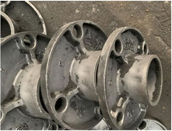
To validate the developed SPH – FEM coupling method, a case study of an extrusion casting bracket part is conducted. The simulation results are compared with experimental data and commercial software results to evaluate the accuracy and reliability of the proposed method.
3.1 Simulation Setup
The bracket part is modeled with its detailed geometry and material properties. The casting and mold materials are specified, along with the process parameters such as the punch pressure, punch velocity, pouring temperature, filling temperature, punch temperature, and holding time. The SPH and FEM models are discretized with appropriate particle and grid sizes to balance computational accuracy and efficiency.
3.2 Filling Process Simulation
The SPH method is used to simulate the filling process of the bracket part. The evolution of the liquid metal front and the temperature distribution during filling are monitored. The simulation results are compared with those obtained from commercial software. As shown in the following figures, the SPH simulation closely matches the commercial software results in terms of the filling pattern and temperature distribution.
| Time (s) | SPH Simulation Result | Commercial Software Result |
|---|---|---|
| 0 | Metal liquid pre-stored in the runner. | Metal liquid pre-stored in the runner. |
| 0.42 | Metal liquid enters the ingate and fills steadily. | Metal liquid enters the ingate and fills steadily. |
| 0.62 | Metal liquid continues to fill, flowing in two directions. | Metal liquid continues to fill, flowing in two directions. |
| 0.79 | Metal liquid fills the casting cavity, with some splashing. | Metal liquid fills the casting cavity, with some splashing. |
| 0.91 | Metal liquid fills further, with complex flow patterns. | Metal liquid fills further, with complex flow patterns. |
| 1.06 | Metal liquid reaches the far end of the cavity, with temperature drop at the edges. | Metal liquid reaches the far end of the cavity, with temperature drop at the edges. |
| 1.18 | The largest cross-section of the casting is mostly filled. | The largest cross-section of the casting is mostly filled. |
| 1.58 | The cavity is completely filled, with a clear shape. | The cavity is completely filled, with a clear shape. |
3.3 Solidification Process Simulation
The FEM method is used to simulate the solidification process of the bracket part. The temperature and stress fields during solidification are analyzed. The cooling rate and effective stress at different locations of the casting are monitored. The results show that the cooling rate is highest at the thin walls on the side of the bracket part, leading to the highest effective stress in these areas.
| Location | Cooling Rate (°C/s) | Effective Stress (MPa) |
|---|---|---|
| Side thin wall (Point a) | Highest | 239.24 |
| Inner concave cavity (Point b) | Moderate | 93.21 |
| Reinforcement root (Point c) | Low | 44.07 |
| Sidewall corner (Point d) | Low | 34.49 |
3.4 Comparison with Experimental Results
Experimental measurements of the temperature and stress fields during the squeeze casting process of the bracket part are conducted. The simulation results are compared with the experimental data to further validate the accuracy of the proposed method. The comparison shows good agreement between the simulation and experimental results, indicating the reliability of the SPH – FEM coupling method for predicting the behavior of the squeeze casting process.
4. Discussion and Analysis
The simulation results provide valuable insights into the squeeze casting process. The flow and temperature fields during the filling process affect the distribution of the liquid metal and the formation of potential defects such as gas entrapment. The temperature and stress fields during the solidification process determine the final microstructure and mechanical properties of the casting. By analyzing the simulation results, the following conclusions can be drawn:
4.1 Filling Process
The SPH method effectively captures the complex fluid flow behavior during the filling process. The slow filling speed and the presence of a free surface are accurately simulated, allowing for the prediction of potential flow-related defects. The comparison with commercial software results validates the accuracy of the SPH model and its ability to provide reliable predictions for the filling process.
4.2 Solidification Process
The FEM method accurately calculates the temperature and stress fields during the solidification process. The sequential solidification pattern observed in the simulation is consistent with the expected behavior of the casting. The highest cooling rate and effective stress at the side thin walls indicate the potential for defect formation in these areas. Understanding the stress distribution during solidification is crucial for predicting and preventing cracking and other defects in the casting.
4.3 Process Optimization
Based on the simulation results, process parameters can be optimized to improve the quality of the squeeze casting. For example, adjusting the punch pressure and velocity can control the filling speed and reduce the likelihood of gas entrapment. Modifying the mold design to enhance heat transfer in critical areas can promote more uniform solidification and reduce stress concentrations. The numerical simulation provides a powerful tool for evaluating different process scenarios and identifying the optimal conditions for squeeze casting.
5. Conclusion
In this study, a numerical simulation method based on the SPH – FEM coupling is developed for the squeeze casting process. The SPH and FEM models are established for the filling and solidification processes, respectively, and a data transfer process is implemented to couple the two methods. The simulation results for a bracket part are validated through comparison with commercial software and experimental data. The following conclusions are obtained:
5.1 SPH – FEM Coupling Method
The SPH – FEM coupling method combines the advantages of the SPH and FEM, providing an accurate and efficient way to simulate the squeeze casting process. The SPH method is suitable for handling the complex fluid flow during the filling process, while the FEM method enables precise calculation of the temperature and stress fields during the solidification process. The coupling between the two methods ensures seamless data transfer and accurate prediction of the overall process behavior.
5.2 Simulation Results Validation
The simulation results for the bracket part show good agreement with the commercial software and experimental data. The filling process simulation using the SPH method accurately predicts the flow and temperature fields, and the solidification process simulation using the FEM method correctly captures the temperature and stress evolution. The validation of the simulation results confirms the reliability of the developed method for practical applications.
5.3 Process Insights and Optimization
The simulation results provide valuable insights into the squeeze casting process, highlighting the areas of potential defect formation and the effects of process parameters on the final product quality. By analyzing the temperature and stress fields, process optimization strategies can be proposed to reduce defects and improve the mechanical properties of the casting. The numerical simulation serves as a powerful tool for understanding and optimizing the squeeze casting process, enabling manufacturers to produce high-quality components with improved efficiency and reduced costs.
Future work can focus on further improving the accuracy and efficiency of the simulation method, extending the application to more complex geometries and materials, and integrating the simulation with other manufacturing processes for a more comprehensive optimization of the production chain.