
In my experience as a casting engineer, the development of efficient and reliable casting processes for critical components like bearing seats is paramount. These structural parts, often made from grey cast iron, serve to support bearings, ensuring precise rotation and reducing friction to enhance equipment longevity and reliability. The accuracy of a bearing seat, particularly its inner bore and base, directly influences transmission precision. Traditional trial-and-error methods for casting process design are time-consuming and resource-intensive. Therefore, I have turned to numerical simulation technology to supplement and optimize these processes. By leveraging software like ProCAST, we can visualize casting dynamics, predict defects, and refine designs before physical production, ultimately improving quality and reducing costs. This article details my approach to optimizing the casting process for a grey cast iron bearing seat upper half through simulation-assisted design, focusing on the material’s unique properties and the implementation of risers and chills.
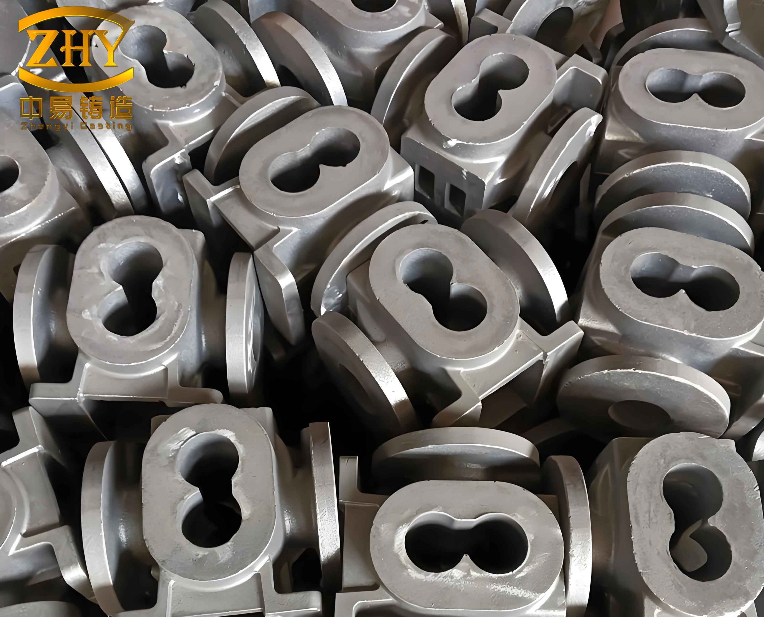
The component in question is a bearing seat upper half with an overall contour size of 1085 mm × 910 mm × 380 mm. It features varying wall thicknesses, with a maximum of 145 mm and a minimum of 20 mm, averaging around 25 mm. This disparity in thickness inherently creates thermal hotspots or hot spots during solidification, which are prone to shrinkage defects like porosity and cavities. The material specified is HT250, a grade of grey cast iron known for its pearlitic matrix and flake graphite morphology. Grey cast iron offers excellent strength, wear resistance, thermal stability, and damping capacity, making it ideal for bearing applications. Its solidification behavior is characterized by the precipitation of primary phases, eutectic transformation, and the final freezing of residual liquid. A key advantage of grey cast iron is the expansion during graphite growth in the eutectic cells, which can compensate for liquid shrinkage, reducing the demand for extensive feeding compared to other alloys. This property is central to designing effective feeding systems for grey cast iron castings.
My initial step involved a thorough casting process design based on the component’s functionality and geometry. For this grey cast iron part, I selected sand casting with manual molding, using acid-cured furan resin self-setting sand for its good thermal resistance and stability, suitable for small-batch production. The coating applied was an alcohol-based powder coating to separate the iron melt from the mold. After evaluating several pouring position schemes, I opted for one where the large base plane is positioned at the bottom. This ensures the quality of critical machined surfaces, facilitates core positioning, and allows thick sections to be placed at the top for easier feeding. The parting plane was set at the bottom face to simplify molding and enhance dimensional accuracy by keeping the entire casting in one half of the mold. The gating system was designed as a bottom-pouring closed type to promote smooth filling and reduce turbulence. The cross-sectional areas were calculated using standard ratios for grey cast iron castings. The choke area was determined first, and then the dimensions for sprue, runner, and ingate were derived. The pouring time was estimated using an empirical formula common for grey cast iron pieces weighing between 100 and 1000 kg:
$$ t = S_1 \sqrt[3]{G_L} $$
where \( t \) is the pouring time in seconds, \( S_1 \) is an empirical coefficient (taken as 1.7 for fast pouring), and \( G_L \) is the total mass of metal in the mold in kg. With a casting mass of 566 kg and a total poured mass of 679.2 kg (1.2 times the casting mass), the calculated pouring time was 46.4 seconds. The gating system dimensions are summarized in the table below:
| Gating System Element | Cross-Sectional Area (cm²) | Dimensions |
|---|---|---|
| Sprue | 10.06 | φ = 36 mm |
| Runner | 9.63 | Rectangular: 32 mm × 30 mm |
| Ingate | 8.75 | Rectangular: 35 mm × 25 mm |
To simulate the casting process, I created a 3D model in SolidWorks and imported it into ProCAST for meshing and analysis. The parameters were set: pouring temperature at 1350°C, pouring time at 46.4 s, and initial mold and core temperature at 20°C. The simulation of filling revealed a sequential bottom-up filling pattern, taking approximately 47.71 seconds to complete, which aligns well with the designed time. The fill time contour showed banded isochrones, indicating uniform and stable flow without excessive turbulence—a positive sign for minimizing oxide inclusions in grey cast iron. Solidification analysis highlighted five major thermal hotspots corresponding to the thickest sections, as expected for this grey cast iron component. Defect prediction without any feeding system confirmed significant shrinkage porosity concentrated in these areas, particularly at the central thickest wall and rear thin-walled regions.
The initial simulation underscored the need for a feeding system to address shrinkage in the grey cast iron casting. Guided by the principle of directional solidification, I designed two insulated top risers and several chills. The riser dimensions were calculated using the modular method, where the riser diameter \( D_R \) and height \( H_R \) are proportional to the thermal modulus of the casting section. For a grey cast iron casting, the formulas are:
$$ D_R = K \cdot T $$
$$ H_R = (1.2 \text{ to } 2.5) \cdot D_R $$
where \( K \) is a coefficient (typically 1.2 to 2.5 for grey cast iron), and \( T \) is the thermal diameter of the hot spot. For the main hot spot with \( T_1 = 66.5 \) mm, I chose \( K = 1.5 \), yielding \( D_{R1} = 100 \) mm and \( H_{R1} = 150 \) mm. For a secondary hot spot with \( T_2 = 50 \) mm, \( D_{R2} = 75 \) mm and \( H_{R2} = 112.5 \) mm. The riser neck dimensions were derived as \( d = (0.8 \text{ to } 0.9) \cdot T \). Additionally, six external chills with a thickness of 10 mm were placed strategically to accelerate cooling in specific areas and enhance directional solidification. The table below summarizes the riser design parameters for this grey cast iron part:
| Riser Label | Hot Spot Diameter, \( T \) (mm) | Riser Diameter, \( D_R \) (mm) | Riser Height, \( H_R \) (mm) | Neck Diameter, \( d \) (mm) |
|---|---|---|---|---|
| Riser 1 | 66.5 | 100 | 150 | 59.85 |
| Riser 2 | 50 | 75 | 112.5 | 45 |
Simulating this optimized setup showed a marked improvement. The defects were reduced in size and number, with much of the shrinkage shifted to the risers, indicating effective feeding for the grey cast iron. However, a significant defect remained near Riser 1’s left side. A temperature field slice analysis revealed a lingering high-temperature zone, forming an isolated liquid pool during solidification. To address this, I added a seventh chill (Chill 7) with a thickness of 30 mm, based on the local hot spot geometry. The secondary optimization simulation demonstrated further reduction in defects, with almost all shrinkage confined to the risers. This confirmed that the combination of risers and chills successfully established directional solidification, leveraging the expansion characteristics of grey cast iron to minimize internal defects.
The effectiveness of the feeding system can be quantified by the feeding distance concepts for grey cast iron. The total feeding distance \( L \) for a section with chills can be estimated as:
$$ L = L_c + L_r $$
where \( L_c \) is the chill contribution and \( L_r \) is the riser contribution. For grey cast iron, \( L_r \) typically ranges from 4.5 to 6 times the section thickness. With chills, \( L_c \) can extend this further. In my design, the placement ensured that all critical sections were within the feeding range, enhancing soundness.
In conclusion, numerical simulation proved invaluable in optimizing the casting process for this grey cast iron bearing seat. By analyzing filling and solidification patterns, I identified defect-prone areas and iteratively improved the design with risers and chills. The final scheme, featuring two insulated risers and seven chills, promoted directional solidification and effectively fed the shrinkage, resulting in a high-quality grey cast iron casting. This approach not only saves time and resources but also provides a deeper understanding of the process dynamics specific to grey cast iron. Future work could explore varying chill materials or advanced simulation of microstructure evolution in grey cast iron. The integration of simulation into casting practice is essential for advancing the production of reliable grey cast iron components like bearing seats.
Throughout this study, the unique properties of grey cast iron, such as its graphite expansion during solidification, were central to the feeding strategy. The use of ProCAST allowed for precise visualization and optimization, ensuring that the final casting meets stringent quality standards. This methodology can be extended to other complex grey cast iron parts, underscoring the versatility of simulation-assisted design in modern foundry engineering.