
The production of large and geometrically complex castings, such as pump volutes or turbine housings, presents significant challenges in sand casting. These challenges are amplified when the material is ductile iron (nodular cast iron), due to its unique solidification behavior. This article details a comprehensive methodology for the process design and optimization of such castings, focusing on leveraging the material’s characteristics to achieve sound, high-quality components efficiently. The core principles discussed are applicable to a wide range of large ductile iron parts produced via sand casting.
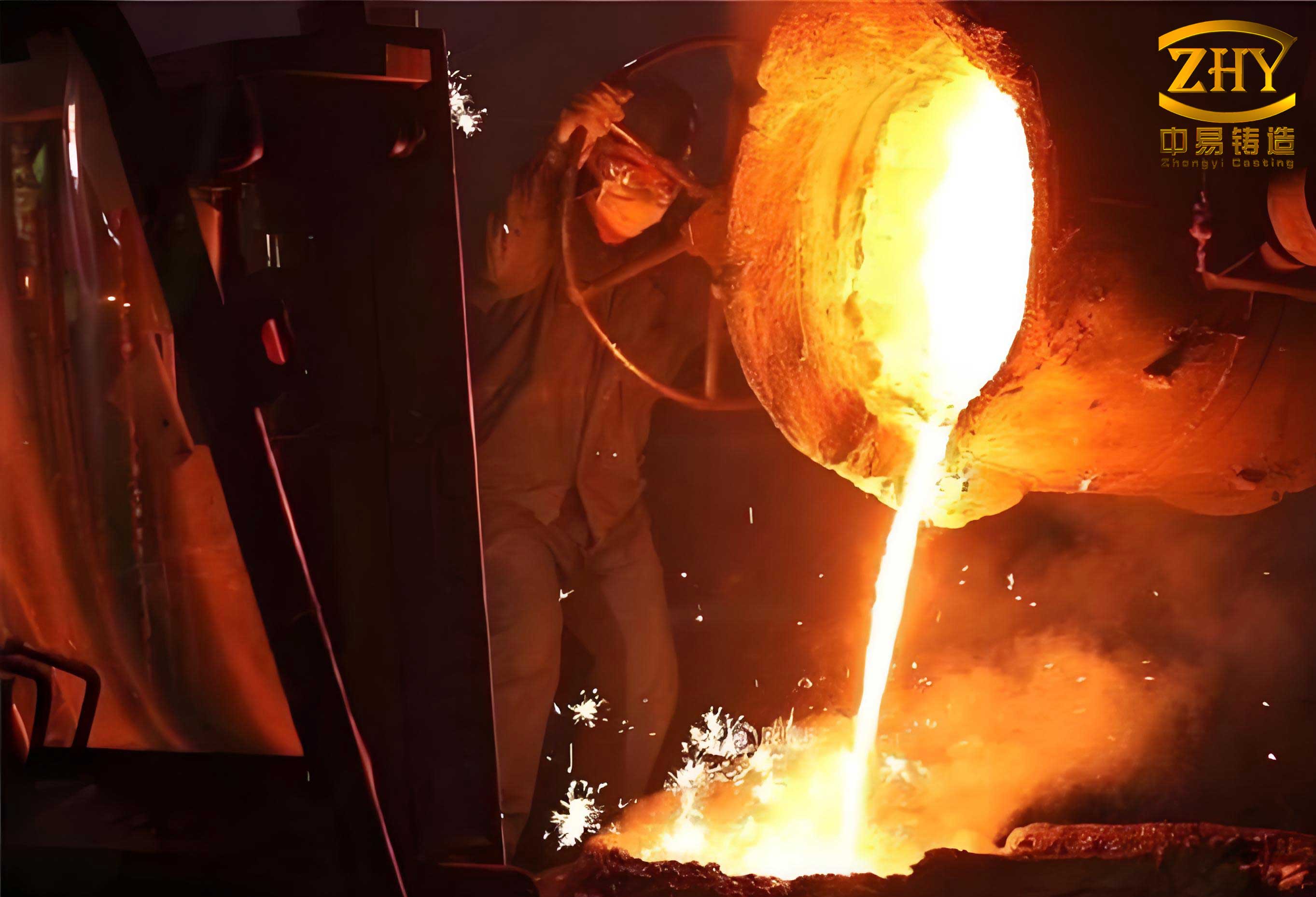
Sand casting remains a dominant and versatile manufacturing process for large metal components. It involves creating a mold cavity by compacting refractory sand around a pattern. For large castings, chemically bonded sands, like furan or phenolic urethane resin sands, are preferred for their high strength, dimensional accuracy, and ability to produce complex geometries without the need for baking. The success of a sand casting process hinges on a synergistic design that considers fluid flow, heat transfer, solidification, and the specific metallurgy of the alloy.
1. Material Characteristics: Ductile Iron Solidification
Ductile iron derives its enhanced mechanical properties from the spheroidal morphology of its graphite particles, achieved through magnesium or cerium treatment. Its solidification differs markedly from that of gray iron or steel, profoundly influencing sand casting工艺 design.
- Graphitization Expansion: During the eutectic solidification phase, the precipitation of graphite (which has a lower density than the liquid iron) causes a volumetric expansion. This expansion can compensate for the shrinkage associated with the phase change from liquid to solid (austenite). The net expansion pressure, $P_{exp}$, can be estimated as a function of the carbon equivalent (CE) and cooling rate.
- Mushy Zone Solidification: Ductile iron solidifies over a wide temperature range, creating a prolonged mushy zone. This necessitates careful thermal management to avoid internal shrinkage porosity.
- Sensitivity to Section Thickness: Variations in cooling rate significantly affect the graphite nodule count, size, and matrix structure. Large differences in section thickness can lead to non-uniform mechanical properties and the risk of shrinkage defects in heavy sections.
The carbon equivalent is a key parameter:
$$ CE = \%C + \frac{1}{3}(\%Si + \%P) $$
A high CE (typically > 4.3 for ductile irons) promotes a strong graphitization expansion potential, which is a critical factor for the riserless (feederless) sand casting approach discussed later.
2. Challenges in Large Ductile Iron Castings
For a large component like a volute, with intricate internal passages and significant variation in wall thickness, the primary challenges in sand casting are:
| Challenge | Description | Consequence |
|---|---|---|
| Non-Uniform Cooling | Thin sections solidify rapidly, while thick sections (bosses, flanges) remain liquid. | Thermal stresses, distortion, and potential hot tears. Inhomogeneous microstructure (graphite distribution). |
| Shrinkage Porosity | Liquid and solidification shrinkage in isolated heavy sections if not properly fed. | Internal defects leading to leakage under pressure and reduced mechanical strength. |
| Filling Defects | Turbulent filling of a large, complex mold cavity. | Sand erosion, oxide formation, gas entrapment, and cold shuts. |
| Mold Strength | High metallostatic pressure and graphitization expansion forces on the mold. | Mold wall movement, dimensional inaccuracy, and swelling defects. |
3. Foundry Process Design and Optimization Strategy
3.1. Casting Orientation and Parting Line Selection
The first critical decision is the orientation of the casting in the mold. For a volute-shaped part, the optimal orientation typically places the largest flat surface or flange at the top and the inlet/outlet openings downward. This strategy offers several advantages in sand casting:
- Improved Soundness of Critical Surfaces: Machined sealing surfaces (e.g., large flanges) are positioned at the top. While gases and slag may collect here, they can be machined away, ensuring the integrity of pressure-containing walls lower down.
- Core Stability: A large, complex internal core can be securely seated and anchored from below, minimizing the need for core prints or chaplets on the upper surface, which can be sources of leakage.
- Simplified Gating: It facilitates the implementation of a bottom-filling gating system.
The parting line should be placed at the largest cross-section of the casting, often through the centerline of the main flanges, to simplify pattern withdrawal and core setting.
3.2. Gating System Design for Controlled Filling and Thermal Management
The gating system must achieve calm, uniform filling and address the thermal gradient issue. A common but suboptimal approach is to place multiple ingates around the volute’s periphery, which can lead to turbulence and temperature stratification.
The proposed optimized strategy involves:
- Location: Positioning the ingates at or near the thinnest major section of the casting, typically adjacent to a flange on the volute’s outlet/inlet. This is counter-intuitive to traditional feeding logic but crucial for ductile iron.
- Rationale: By introducing hot metal into the thinner section, its solidification is delayed. This action reduces the temperature difference ($\Delta T$) between thick and thin areas, promoting more simultaneous solidification. The goal is to minimize the thermal gradient, expressed as:
$$ \Delta T = T_{pour} – \left( \frac{dT}{dt}_{thick} \cdot t_{solid, thin} + T_{solidus} \right) $$
Where $dT/dt_{thick}$ is the cooling rate in the thick section and $t_{solid, thin}$ is the solidification time of the thin section. A smaller $\Delta T$ promotes uniform graphite formation.
- Pathway: Metal flows from the downsprue, through a runner system, into ingates that lead into a thin flange section. It then naturally follows the spiral volute channel upwards, filling the cavity smoothly from the bottom in a progressive manner. This minimizes turbulence and aids in slag flotation towards the top of the mold cavity.
| Gating Scheme | Ingate Location | Advantages | Disadvantages |
|---|---|---|---|
| Peripheral Top-Filling | Multiple points around outer volute wall | Simple patternmaking | High turbulence, temperature gradient, slag entrapment in critical walls |
| Direct Bottom-Filling | Base of large opening | Calm filling | Complex core/mold design, potential for hot spots at ingate |
| Optimized Bottom-Filling (Proposed) | At thin section near flange | Reduces thermal gradient, calm filling, promotes directional solidification towards top, aids slag flotation | Requires precise simulation and thermal analysis |
3.3. The Riserless (Feederless) Casting Approach
For large ductile iron castings with a high Carbon Equivalent and a favorable geometry, it is possible to eliminate traditional risers (feeders). This is a cornerstone of advanced sand casting for this material. The success relies on creating conditions for “self-feeding” via graphitization expansion.
Requirements for Successful Riserless sand casting:
- Adequate Mold Strength: The mold, made from high-strength resin-bonded sand and often reinforced with steel frames or jackets, must be rigid enough to withstand the internal expansion pressure ($P_{exp}$) without wall movement. Wall movement would create space for shrinkage porosity to form.
- Controlled Solidification Sequence: The casting must solidify directionally from the extremities (points farthest from the ingates) back towards the ingates, and the ingates themselves must freeze before the heavy sections in the casting. This “seals” the casting, creating a closed volume.
- Exploitation of Graphitization Expansion: Once sealed, the ongoing graphite precipitation within this closed volume generates internal pressure that compensates for residual liquid/solidification shrinkage in the heavy sections. The pressure balance is critical:
$$ P_{exp} \ge P_{shrink} + P_{atm} $$
Where $P_{shrink}$ is the pressure drop due to shrinkage formation and $P_{atm}$ is atmospheric pressure. A rigid mold ensures $P_{exp}$ is effectively applied to the solidifying metal.
- Use of Chills: Internal (core) or external chills are strategically placed on heavy sections (like thick flanges or bosses). Chills accelerate local cooling, effectively increasing the local modulus ($M$) to match that of thinner adjacent areas. The modulus is defined as:
$$ M = \frac{V}{A} $$
where $V$ is volume and $A$ is the surface area through which heat is lost. By reducing the solidification time of a heavy section, chills help synchronize the solidification front and prevent the formation of isolated liquid pools.
<ol sand casting design.
- Thin sections and chills solidifying first.
- A directional solidification pattern moving from the extremities back towards the ingates.
- The ingate regions freezing before the central heavy sections of the casting.
- Isothermal lines that are as parallel as possible, indicating uniform cooling.
The solidification time ($t_s$) for a section can be approximated by Chvorinov’s rule, useful for initial design:
$$ t_s = B \cdot \left( \frac{V}{A} \right)^n = B \cdot M^n $$
where $B$ and $n$ are constants dependent on mold material and metal properties.
$$ NY = \frac{G}{\sqrt{\dot{T}}} $$
Areas with a $NY$ value below a critical threshold are prone to microporosity.
The simulation provides a virtual proof, reducing the need for multiple expensive and time-consuming physical trials in the sand casting foundry.
5. Conclusion: The Integrated Optimization Approach
The production of high-integrity large ductile iron castings via sand casting requires an integrated design philosophy that moves beyond conventional rules. The optimized strategy synthesizes several key principles:
- Thermal Gradient Control through Gating: Placing ingates at thin sections to equalize cooling rates and promote uniform graphite formation.
- Exploitation of Intrinsic Material Behavior: Harnessing the graphitization expansion of ductile iron within a rigid mold system to achieve self-feeding, enabling riserless production for significant yield improvement and cost reduction.
- Strategic Use of Auxiliary Cooling: Applying chills to modulate solidification times of heavy sections, synchronizing the overall solidification front.
- Simulation-Driven Design: Utilizing numerical modeling to virtually prototype and validate the filling, solidification, and defect formation outcomes before committing to tooling and melt.
This holistic approach to sand casting process design ensures an optimal match between the geometric possibilities of the process, the unique metallurgy of ductile iron, and the economic demands of manufacturing. It results in castings with superior metallurgical uniformity, pressure tightness, and mechanical properties, while simultaneously reducing costs associated with melting extra metal for risers, cleaning, and scrapping defective parts. The methodology underscores that advanced sand casting is a precise engineering discipline, where every element—from gating location to mold rigidity—is a critical variable in a tightly coupled system.