
BBased on the combination of mold materials and modeling methods, the composite mold can be divided into several units according to the structural characteristics of the motor end cover casting. Each mold unit can be modeled by traditional pattern modeling, sand mold 3D printing and sand mold NC milling. The mold assembly adopts box modeling. Among them, the division of upper and lower types is based on the parting line in Figure 1. Above the parting line is the upper type (punch) and below is the lower type (concave die). The wall thickness at the junction of the end stiffener and the center of the casting is thin, which is prone to shrinkage and porosity defects of the internal structure. In addition, in order to ensure that the end face has sufficient strength and stiffness, the post-processing of this area should be avoided as far as possible. Therefore, sand mold 3D printing is adopted for the main part of the upper mold casting to adapt to the forming of complex mold surface with multi fillet and multi groove features in the upper mold.

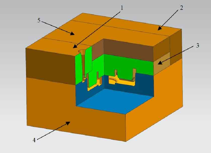
The lower mold structure of the mold is relatively regular and simple, which is completed by sand mold NC milling. The gating system and feeding riser are the last cut-off part. Only the mold filling function needs to be correctly realized, that is, the turbulence is minimized, the mold filling is complete, and the correct solidification sequence is provided, which can appropriately reduce the accuracy requirements. Usually, the foundry has its own gating system design rules to adapt to the modeling work of various castings. Using the existing wood mold or making a new mold can save a lot of development time and cost, which not only avoids the complex casting structure, but also the gating system structure is relatively simple. Therefore, this part is realized by traditional pattern modeling method. However, the inner sprue is directly connected with the casting. In order to avoid flash, burr and other defects, the mold where the gating system is located is divided along the inner contour of the transverse sprue, and matched with the upper mold body through the step structure. The specific mold structure is shown in Figure 2:
The specific process parameters of the casting produced by the composite forming method before optimization are set, and the forming of the composite mold is based on 650mm × 650mm × For 300mm sand box, the casting yield under the original process design scheme is 84.83%, and the sand filling volume of the remaining part of the sand box is 0.0219m3. The size parameters of mold module before optimization based on compound forming.