The process of rapid sand casting technology to realize the rapid manufacturing of parts is as follows: establish the three-dimensional model of the casting; Complete the mold CAD model and casting process design; Using numerical simulation (based on ProCAST software) analyze and verify the mold design; make SLA pattern and core box with light curing prototype equipment; assemble and assemble SLA prototype mold; make sand mold and pour the casting. The establishment of mold CAD model is realized by the specially developed rapid sand mold casting process CAD system to complete the casting process Process parameter design, gating system design, feeding system design, etc.
1. Three dimensional model and material properties of cylinder head
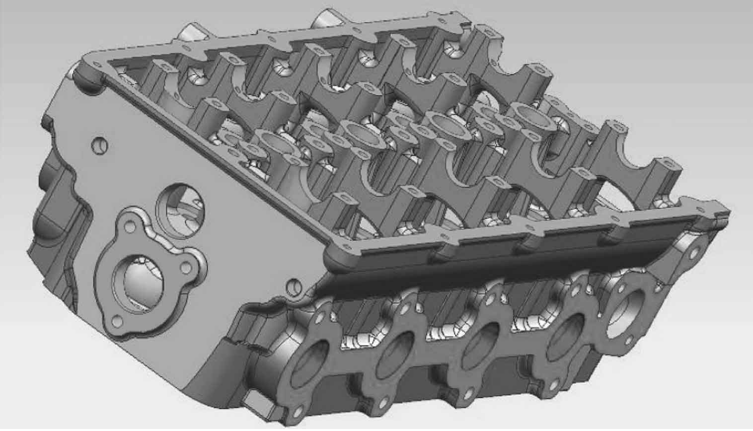
The three-dimensional model of engine cylinder head modeled by ugnx8.0 software is shown in Figure 1. The cylinder head of the engine is made of ZL105 aluminum alloy with good casting performance. See Table 1 for its chemical composition.
2. Casting process design
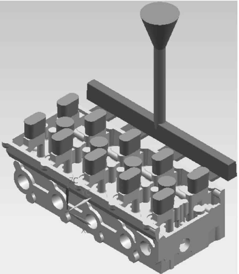
Selection of casting parting surface: ① it can ensure the smooth production and removal of sand core; ② Reduce the number of parting surfaces as much as possible to ensure the structural and dimensional accuracy of the product; ③ Plane parting shall be adopted as far as possible to avoid or reduce the deformation error of curve parting surface. According to the structure of cylinder head, the sand core is divided into lower left oil channel core, lower right oil channel core, water channel core, upper oil channel core, inlet channel sand core and exhaust channel sand core. When designing the gating system, select the gating system structure, determine the pouring position and calculate the sectional area of each sprue according to the casting structure, technical requirements and alloy type. Single side bottom pouring is adopted, and the liquid metal enters from the bottom, which can avoid the direct impact of the liquid metal on the molding sand, and the liquid level rises gently. According to the structural characteristics of the casting, the waist shaped open riser is selected and set on the upper box. CAD system is used to automatically calculate the riser module, and determine the heat dissipation volume, heat dissipation surface area, number of risers, feeding efficiency and other relevant parameters. The casting process parameters are determined according to relevant theories and standards, in which the mold starting inclination and linear shrinkage are re determined according to the characteristics of light curing forming. The designed mold CAD model is shown in Figure 2.


