
In my extensive experience with lost foam casting, one of the most persistent and costly defects encountered is mold collapse, often referred to as塌箱,塌型, or溃散. This defect manifests as the partial or complete collapse of the dry sand mold during pouring or solidification, leading to incomplete casting formation or excess metal in localized areas. The inherent nature of the lost foam casting process, which utilizes unbonded dry sand compacted by vibration, makes it particularly susceptible to such collapses, especially when producing large flat plates or castings with enclosed or semi-enclosed cavities. The high gas generation from the vaporizing foam pattern, coupled with insufficient mold strength, can create a critical pressure imbalance, causing the mold to fail. Recently, during the production of furnace baffle plates for a steelmaking upgrade project, severe pouring collapse defects were observed, resulting in a yield rate of less than 70%. Through a systematic analysis and targeted improvements in the gating system, in-mold vacuum degree, and coating strength, the collapse issue was effectively resolved. This article details my first-hand approach and the technical rationale behind these modifications, aiming to provide a comprehensive guide for practitioners facing similar challenges in lost foam casting.
The production of large, flat gray iron components like furnace baffle plates presents unique difficulties in lost foam casting. These plates, designed as fixed fireproof barriers on both sides of a converter, are critical for safety, preventing slag splashes during steelmaking. Unlike smaller, thinner furnace doors, these baffle plates are substantial in size, typically measuring 1626 mm × 1400 mm × 40 mm, with weights ranging from 240 kg to 380 kg, and are made of HT150 gray iron. To minimize distortion during casting, the patterns were designed in pairs, spaced 250 mm apart, with six 40 mm × 40 mm anti-distortion ribs connecting them. The original lost foam casting process utilized Expanded Polystyrene (EPS) patterns with a density of 18 kg/m³. The gating system was located on one side of the pattern cluster, featuring a sprue of φ50 mm, a runner of 50 mm × 50 mm, and ingates with a total cross-sectional area of 15 mm × 50 mm (7.5 cm² per ingate). The molds were assembled in a flask with internal dimensions of 2370 mm × 1170 mm × 1100 mm, supplemented with a 700 mm high extension box. Two sets of pattern clusters (four plates total) were arranged side-by-side with a 200 mm gap. To enhance vacuum within the mold cavity, a single φ60 mm removable pipe was inserted between the patterns in each cluster. The pouring parameters included a temperature of 1360°C, a pouring time of approximately 28 seconds, a pre-pour vacuum of -0.060 MPa, and a post-pour vacuum of -0.050 MPa, held for 8 minutes after pouring. Despite this setup, the collapse defect rate reached about 30%, necessitating a thorough investigation.
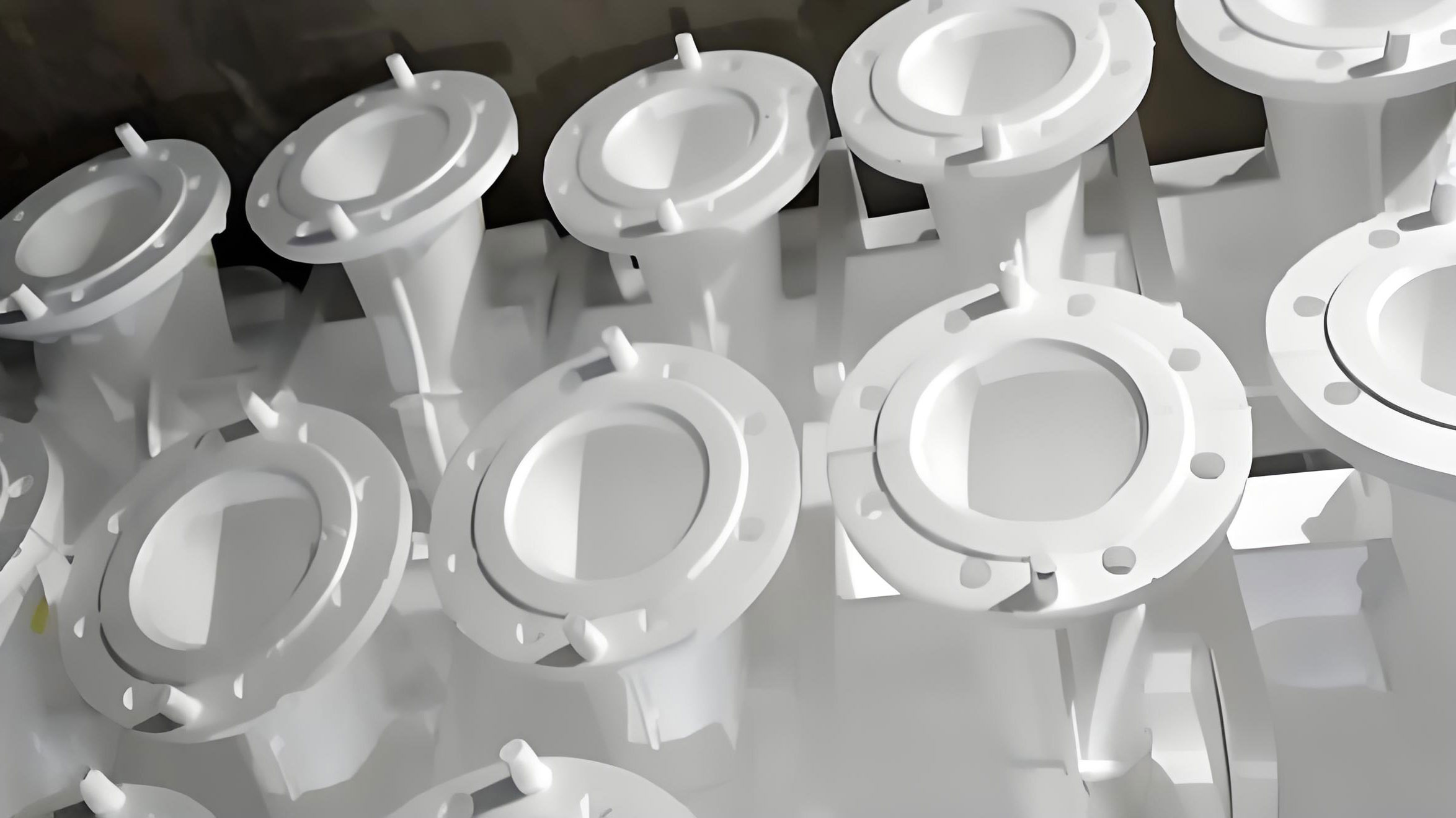
The root causes of mold collapse in lost foam casting are often multifaceted. My analysis focused on four key areas: the gating system design, pouring sequence, in-mold vacuum effectiveness, and coating properties. A critical step was to theoretically verify the gating dimensions. For lost foam casting, the ingate cross-sectional area must be carefully calculated to control metal velocity and flow rate, preventing rapid foam degradation and excessive gas generation. The basic formula for calculating the ingate area \(A\) (in cm²) is derived from fluid dynamics principles:
$$A = \frac{G}{0.17 \cdot t \cdot \sqrt{H_p}}$$
where \(G\) is the casting weight (kg), \(t\) is the pouring time (s), and \(H_p\) is the effective metallostatic head height (cm), typically taken as half the casting height. For a 380 kg casting with a height of 40 mm (4 cm), \(H_p = 0.5 \times 4 = 2\) cm. The pouring time \(t\) is often estimated as \(t = s \sqrt{G}\), with the coefficient \(s\) ranging from 1.5 to 2.0 for gray iron in lost foam casting; using \(s = 1.7\) as a reference:
$$t = 1.7 \times \sqrt{380} \approx 33.14 \text{ seconds}$$
Substituting into the formula:
$$A = \frac{380}{0.17 \times 33.14 \times \sqrt{2}} \approx \frac{380}{0.17 \times 33.14 \times 1.414} \approx \frac{380}{7.96} \approx 7.11 \text{ cm}^2$$
It is a well-established practice in lost foam casting to increase the gating area by 20-30% compared to conventional sand casting to accommodate foam decomposition gases. Applying a 20% increase:
$$A_{\text{corrected}} = 7.11 \times 1.20 \approx 8.53 \text{ cm}^2 \approx 9 \text{ cm}^2 \text{ total}$$
Therefore, the required ingate area per plate (assuming two ingates) should be approximately 4.5 cm². The original design had a total area of 15 cm² (7.5 cm² per ingate), which was 66% larger than the calculated requirement. This excessive area led to a high pouring velocity, causing rapid, violent foam gasification. The instantaneous gas generation rate \(Q_g\) (in m³/s) can be conceptually related to the metal flow rate \(Q_m\) and the foam density \(\rho_f\) by:
$$Q_g \propto \frac{Q_m}{\rho_f} \cdot \Delta T$$
where \(\Delta T\) is the temperature difference. A higher \(Q_m\) from a larger ingate area increases \(Q_g\), potentially overwhelming the vacuum system’s evacuation capacity and creating a high positive pressure inside the mold cavity relative to the surrounding sand, leading to collapse.
Secondly, the pouring sequence was problematic. The original setup used a vertical step-gating arrangement with two ingates aligned one above the other. In lost foam casting, this can cause a “flashing flow” phenomenon, where metal initially enters through the upper ingate, creating an unstable and uneven front that can erode the partially vaporized foam pattern and destabilize the mold wall before the lower section is filled. This violates the desired bottom-up filling sequence crucial for stable mold integrity in lost foam casting.
Thirdly, the in-mold vacuum degree was insufficient. Vacuum is essential in lost foam casting to compact the dry sand, remove decomposition gases quickly, and maintain mold stability. The vacuum level measured at the system gauge was -0.060 MPa, but the actual vacuum within the mold cavity, especially between the pattern clusters, was significantly lower due to resistance posed by the foam patterns and the sand. To quantify this, a simple probe was constructed using a φ20 mm steel tube with φ5 mm holes wrapped in a stainless steel mesh. When inserted between the patterns and connected to a vacuum gauge, the measured pressure ranged from -0.045 MPa to -0.035 MPa, a 25-42% reduction from the gauge value. The vacuum gradient \(\nabla P\) across the mold can be described by Darcy’s law for flow through porous media:
$$v = -\frac{k}{\mu} \nabla P$$
where \(v\) is the filtration velocity, \(k\) is the permeability of the sand, and \(\mu\) is the gas viscosity. A low \(\nabla P\) (i.e., small pressure difference between the cavity and vacuum source) results in a low gas evacuation velocity \(v\), allowing pressure to build up inside the cavity. The single pipe arrangement was inadequate to maintain a uniform, high vacuum throughout the large mold volume, especially in the central regions between patterns.
Finally, the coating strength was suboptimal. The coating in lost foam casting serves as a barrier between the metal and sand, allowing gases to pass while providing mechanical strength to the mold wall. The original coating formulation had a weight ratio of high-alumina bauxite to Guilin #5 sand of 10:1, with a thickness of 2.0-2.5 mm. After drying for three days, the coating felt soft, indicating insufficient binder content and low strength. The coating’s mechanical strength \(\sigma_c\) can be approximated as a function of binder content \(C_b\), thickness \(d\), and particle packing density:
$$\sigma_c \propto C_b \cdot d \cdot \phi$$
where \(\phi\) is a packing factor. A weak coating is more prone to erosion or cracking under the thermal and mechanical stresses of pouring, leading to local sand invasion and initiating a collapse.
The following table summarizes the identified issues and their mechanisms related to mold collapse in this lost foam casting operation:
| Factor | Original Condition | Problem Mechanism | Impact on Mold Collapse |
|---|---|---|---|
| Ingate Area | 15 cm² total (7.5 cm² each) | Exceeds theoretical requirement by ~66%. Causes high metal velocity and rapid gas generation. | Creates high instantaneous gas pressure, overwhelming vacuum evacuation. |
| Pouring Sequence | Vertical step gates (aligned) | Promotes “flashing flow” – metal enters top gate first. | Causes unstable, top-down filling, eroding foam and destabilizing mold walls. |
| In-Mold Vacuum | Gauge: -0.060 MPa; Actual cavity: -0.035 to -0.045 MPa | Single pipe, pattern resistance causes significant vacuum drop. | Insufficient sand compaction and gas removal, low mold strength. |
| Coating Strength | Binder ratio 10:1, Thickness 2.0-2.5 mm | Low binder content, moderate thickness. | Weak barrier prone to thermal stress, leading to local failure and sand incursion. |
Based on this analysis, a multi-faceted improvement plan was implemented for the lost foam casting process. The primary goal was to balance the gas generation rate with the evacuation capacity and enhance the mold’s structural integrity.
1. Gating System Redesign: The total ingate cross-sectional area was reduced from 15 cm² to 9 cm², aligning with the theoretical calculation. Each ingate was resized to 10 mm × 45 mm (4.5 cm²). To eliminate the “flashing flow” and establish a controlled bottom-up filling sequence, the orientation of the ingates was modified. The lower ingate remained perpendicular to the casting, while the upper ingate was angled upwards at 45°. This geometry ensures that during pouring, metal first enters through the lower ingate. Only after the metal level rises to reach the upper ingate does it begin to feed from there. This promotes a stable, progressive filling front, minimizing turbulence and sudden gas release. The modified gating layout significantly optimizes the fluid dynamics in lost foam casting.
2. Enhancement of In-Mold Vacuum: To address the vacuum attenuation, the vacuum piping inside the mold was reconfigured. Instead of a single removable pipe per pattern cluster, a dual-pipe arrangement was installed in the space between the two pattern clusters. These pipes were connected to the vacuum system, creating multiple evacuation paths and reducing flow resistance. The improved layout aimed to minimize the pressure drop \(\Delta P_{\text{drop}}\) between the vacuum source and the mold cavity, which can be expressed as:
$$\Delta P_{\text{drop}} \propto \frac{L \cdot Q}{n \cdot A_p \cdot k}$$
where \(L\) is the flow path length, \(Q\) is the gas flow rate, \(n\) is the number of pipes, \(A_p\) is the pipe’s permeable area, and \(k\) is permeability. Increasing \(n\) (number of pipes) directly reduces \(\Delta P_{\text{drop}}\), helping maintain a cavity vacuum closer to the system gauge reading. Additionally, the sandbox’s vacuum holes were meticulously inspected and cleaned to ensure no blockages, maximizing evacuation efficiency.
3. Coating Reinforcement: The coating formulation and application were strengthened. The binder content was increased by adjusting the high-alumina bauxite to Guilin #5 sand ratio from 10:1 to 10:1.1. The coating thickness was increased to a range of 2.5 mm to 3.0 mm. These changes aimed to boost the coating’s green strength and thermal resistance. The enhanced coating acts as a more robust semi-permeable membrane, better withstanding the thermal shock of molten iron and the abrasion from sand, thereby maintaining the integrity of the mold cavity walls for a longer duration during the critical pouring and solidification phases of the lost foam casting process.
The table below contrasts the key process parameters before and after the improvements in the lost foam casting of the baffle plates:
| Process Parameter | Original Process | Improved Process | Rationale for Change |
|---|---|---|---|
| Ingate Total Area | 15 cm² | 9 cm² | Match theoretical calc. (~9 cm²), reduce flow velocity. |
| Ingate Design | Vertical, aligned | Lower: vertical; Upper: 45° upward | Ensure bottom-up filling, prevent flashing flow. | Calculated Pouring Time | ~28 s (based on practice) | ~33-35 s (theoretical t=33.14 s) | Slower, controlled filling matches foam gasification rate. |
| In-Mold Vacuum Piping | Single pipe per cluster | Dual pipes between clusters | Reduce flow resistance, maintain higher cavity vacuum. |
| Target Cavity Vacuum | Not measured directly | Close to gauge (-0.06 to -0.05 MPa) | Ensure sufficient sand compaction and gas evacuation. |
| Coating Binder Ratio (Bauxite:Sand) | 10:1 by weight | 10:1.1 by weight | Increase bonding strength. |
| Coating Thickness | 2.0-2.5 mm | 2.5-3.0 mm | Enhance mechanical and thermal barrier. |
After implementing these modifications in the lost foam casting process, the results were immediately observable. The pouring time naturally extended to the range of 33 to 35 seconds, aligning perfectly with the theoretical calculation. The metal flow was visibly calmer and more controlled. Measurements indicated that the difference between the system gauge vacuum and the in-cavity vacuum was minimized, with both维持在 around -0.06 MPa to -0.05 MPa during pouring. The enhanced coating, after drying, exhibited significantly higher hardness and resilience to handling. Most importantly, the mold collapse defect was completely eliminated. Subsequent production batches achieved a yield rate close to 100% for dimensional soundness, with no incidents of塌箱. This success underscores the importance of a holistic, quantitatively-guided approach in troubleshooting lost foam casting defects.
The collapse defect in lost foam casting is a complex interplay of hydrodynamic, thermodynamic, and mechanical factors. This case study demonstrates that effective resolution requires moving beyond empirical adjustments to a principle-based analysis. Key takeaways from this experience with lost foam casting include: Firstly, the gating system must be precisely sized using established formulas, with careful consideration of the unique requirements of lost foam casting, such as the increased gas generation. The ingate area directly controls the metal entry velocity \(v_m\), which should be balanced against the foam decomposition rate. A useful rule-of-thumb is to keep the initial metal velocity below 1 m/s for large flat castings in lost foam casting. Secondly, the filling sequence must be engineered to be bottom-up and laminar. Angled or stepped gating can be effective tools. Thirdly, vacuum effectiveness is not guaranteed by the pump setting alone. The actual pressure within the mold cavity must be considered, and the vacuum distribution system (pipes, holes) must be designed to minimize pressure drops, especially for large or complex molds in lost foam casting. The vacuum level must be sufficient to compact the sand, providing a confining pressure \(\sigma_v\) that counteracts the internal gas pressure \(P_g\). A simple stability criterion can be considered: collapse is less likely if \(\sigma_v + \tau_c > P_g\), where \(\tau_c\) is the cohesive strength of the coating-sand interface. Finally, the coating is not merely a permeable layer but a structural component. Its strength, permeability, and thickness must be optimized for the specific casting geometry and pouring conditions in lost foam casting.
In conclusion, preventing mold collapse in lost foam casting, particularly for challenging geometries like large gray iron flat parts, demands a systematic investigation of all process variables. By focusing on the gating system design to regulate flow, enhancing in-mold vacuum uniformity to ensure gas evacuation and sand stability, and fortifying the coating to act as a robust mold wall, the collapse defect can be successfully mitigated. This integrated approach, grounded in fundamental principles of fluid flow, heat transfer, and mechanics, is essential for advancing the reliability and economic viability of the lost foam casting process for industrial applications. Future work could involve computational modeling of the coupled phenomena—foam degradation, gas flow, and mold stresses—to further optimize lost foam casting processes for even more complex components.