1. Introduction
Lost foam casting, a revolutionary casting process, has gained significant popularity in recent years due to its numerous advantages over traditional casting methods. It offers high precision in casting dimensions, excellent repeatability, great flexibility in production, and superior internal quality of the castings. Since the expiration of its patent in 1980, lost foam casting technology has witnessed rapid growth worldwide and has now reached a relatively mature stage both domestically and internationally. This process is particularly well-suited for the production of complex shell components.
In this article, we will focus on the application of lost foam casting technology in shell castings. We will analyze the main issues that currently arise during the production of shell-like products using this technology and delve into several common casting defects, including their root causes and corrective measures. Specifically, during the casting process of shell castings such as flywheel housings, defects like sand burning, porosity, and sand washing may occur. We will take flywheel housings and other products as examples to illustrate the formation reasons and improvement strategies for these defects.
2. Analysis of Sand Burning Defects in Castings
2.1 Cause of Sand Burning Defects
Sand burning is a defect that occurs when the molten metal adheres to the molding sand on the surface of the casting during the pouring process. In the case of flywheel housing castings, improper placement, structural design, or process design can lead to insufficient compaction of the pattern cluster within the sand box, resulting in sand burning.
The current production of the 9661 flywheel housing, made of HT250 with a mass of approximately 22 kg and dimensions of 440 mm × 440 mm × 220 mm, has a wall thickness of 5 mm. This product has characteristics such as a large surface area, thin base wall thickness, and susceptibility to deformation. The existing process is illustrated in Figure 1, with the inner runner dimensions being 50 mm (length) × 30 mm (height) × 6 mm (width). The molten iron is tapped at a temperature between 1460 and 1470 °C (using an electric furnace for melting), poured at a temperature between 1430 and 1440 °C, under a vacuum of -0.025 MPa, without film coating or pressure retention. The main defect is sand inclusions on the top of the inner cavity of the flywheel housing, with a rejection rate of 20%.
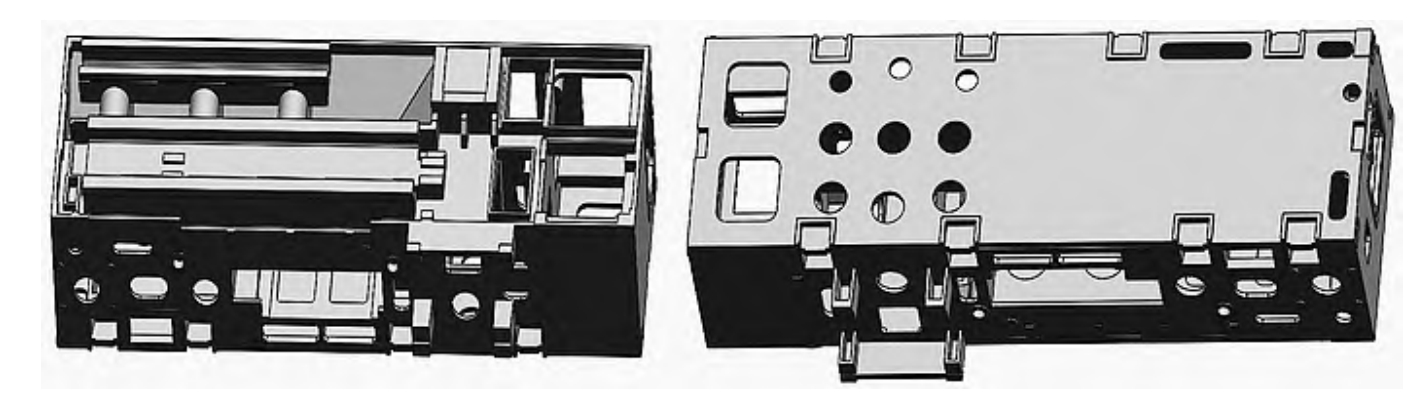
As shown in Figure 2, in the current process, the motor hole is located at the bottom. This often leads to sand burning issues on the top of the inner cavity, as depicted in Figure 3. The reason for this is that the top angle is greater than 90°, preventing the molding sand from being compacted during vibration. As a result, the sand on the top is relatively loose, and during the filling of the molten iron, local metal and sand adhere to each other, causing sand burning.
2.2 Analysis of Flywheel Housing Sand Burning
The sand burning on the 9661 flywheel housing appears as a mechanical mixture of sand grains and metal adhering to the housing surface. When cleaned, the surface exhibits a metallic luster, which is a characteristic of mechanical sand burning. The main factors influencing this defect are the compactness of the molding sand during molding, the fire resistance of the coating, the pouring temperature, and the coating thickness. Since the casting is only affected by sand burning on the top and is normal elsewhere without any sand burning marks, it is considered to be an issue with the compactness of the molding sand. The possible reasons are as follows:
- The top of the flywheel housing cannot be filled with sufficient molding sand, or the existing molding sand cannot be compacted effectively.
- The gap between the two flywheel housings is too small, leading to weak sand strength.
2.3 Control Measures
To address the sand burning issue, the following measures can be taken based on the formation mechanism and influencing factors:
- Adjust the placement of the white pattern according to the product structure. Place the motor hole of the flywheel housing upwards to facilitate the filling of molding sand and ensure an adequate amount of sand on the top of the flywheel housing.
- Increase the distance between the two flywheel housings. Change the original distance of 80 mm to 120 mm to ensure sufficient space between the two pattern clusters, thereby enhancing the compactness of the molding sand.
2.4 Production Verification
After analyzing the causes of the sand compactness problem in the flywheel housing and implementing the corrective measures of adjusting the product placement and combination spacing, production verification was carried out. During the normal production process, while ensuring that variables such as the dipping process, pouring temperature, and vacuuming remained unchanged, production was carried out in small batches and gradually scaled up to large batches. The result showed that the sand burning defect was completely eliminated, achieving the goal of resolving the sand burning issue on the top of the flywheel housing.
3. Analysis of Porosity Defects in Flywheel Housing Castings
3.1 Cause of Porosity Defects
Porosity in castings occurs when the gas and residues generated by the vaporization and decomposition of the white pattern cannot be discharged in a timely manner after the molten iron enters the pattern cluster, resulting in the formation of pores on the casting surface. The occurrence of porosity is related to factors such as pouring temperature, coating permeability, and pouring speed.
The product in question is the flywheel housing for SAIC Maxus. The porosity defect is shown in Figure 5. The molten iron is tapped at a temperature between 1460 and 1470 °C (using an electric furnace for melting), poured at a temperature between 1430 and 1440 °C, under a vacuum of -0.025 MPa, without film coating or pressure retention. The main defect is porosity in the motor hole on the top of the product, with a rejection rate of 30%.
3.2 Influencing Factors
The porosity defect in this case is characterized by the presence of smooth holes of varying sizes on the surface or near the surface of the casting after machining, with the hole walls showing an oxidized color. The pores are mainly concentrated on the top of the product, which is a typical feature of subcutaneous porosity. The main influencing factors are as follows:
- Pouring temperature: When the pouring temperature is too low, the foam does not burn completely, and the gas is not fully discharged, leading to the formation of pores under the skin.
- Local coating thickness: If the coating on the motor hole is too thick, the gas generated after the foam burns cannot be discharged, resulting in porosity.
- Vacuum degree: Insufficient vacuuming causes the gas to not be removed in a timely manner, leading to the formation of pores.
- Process design: The lack of an exhaust port on the top of the flywheel housing causes the gas to accumulate on the top of the casting and not be fully discharged, resulting in porosity.
3.3 Control Measures
To address the porosity issue, the following measures can be taken based on the formation mechanism and influencing factors:
- Increase the pouring temperature from 1430 – 1440 °C to 1450 – 1460 °C and conduct 10 pourings.
- Reduce the coating thickness at this location from 2.0 mm to 0.5 mm and conduct 10 pourings.
- Increase the vacuum degree from -0.025 MPa to -0.045 MPa and conduct 10 pourings.
- Add an exhaust piece at the motor hole with dimensions of 50 mm (length) × 30 mm (height) × 5 mm (width) and conduct 10 pourings.
3.4 Production Verification
After analyzing the causes of the porosity problem in the flywheel housing and implementing the corrective measures of adjusting the process parameters such as pouring temperature, coating thickness, vacuum degree, and adding an exhaust piece, production verification was carried out. During the process test, the control variable method was used, ensuring that the other three process parameters remained unchanged while testing each measure separately. The results are as follows:
- Scheme 1 (increasing pouring temperature): 20 pieces were produced and machined, with 4 pieces having porosity, and the porosity ratio in the motor hole was 20%.
- Scheme 2 (reducing coating thickness): 20 pieces were produced and machined, with 5 pieces having porosity, and the porosity ratio in the motor hole was 25%.
- Scheme 3 (increasing vacuum degree): 20 pieces were produced and machined, with 3 pieces having porosity, and the porosity ratio in the motor hole was 15%.
- Scheme 4 (adding an exhaust piece): 20 pieces were produced and machined, with 0 pieces having porosity, and the porosity ratio in the motor hole was 0%.
The test results showed that Scheme 4 was the most effective. Subsequent small-batch to large-batch verification also confirmed that all processed parts were normal. Through these measures, the goal of completely eliminating the porosity in the motor hole was achieved, and the final process is shown in Figure 6.
4. Analysis of Sand Washing Defects in Connecting Rod Bracket Castings
4.1 Cause of Sand Washing Defects
Sand washing defects can occur during the casting process due to incomplete sealing of the gating system, including the sprue, runner, and ingate, especially in the sprue, which is prone to siphoning. Additionally, an unreasonable design of the product’s gating system can lead to non-smooth filling, resulting in high local pressure in the ingate. This can cause the coating to crack due to the scouring of the molten iron, allowing the molding sand to enter the cavity of the pattern cluster along with the molten iron, thereby causing sand washing defects.
The gating system of the connecting rod bracket casting is shown in Figure 7. The product is made of HT200, with a mass of approximately 50 kg and dimensions of 572 mm × 380 mm × 348 mm. The bottom plate thickness is 12 mm. The existing process involves introducing the molten iron through three side ingates, with the ingate dimensions being 60 mm × 30 mm × 6 mm. The process parameters are as follows: the molten iron is tapped at a temperature between 1460 and 1470 °C (using an electric furnace for melting), poured at a temperature between 1430 and 1440 °C, under a vacuum of -0.03 MPa, without film coating or pressure retention. The main defect is sand washing, which is concentrated near the bottom ingate (Figure 8), with a rejection rate of 20%.
4.2 Influencing Factors
The sand washing defect is characterized by the presence of a mass of sand and metal mixture at the bottom of the cavity along the pouring gate and the area where the molten iron enters the cavity through the ingate. The main influencing factors are as follows:
- Low coating strength of the ingate: The scouring of the molten iron can cause the coating to crack.
- High pressure in the ingate: This can lead to coating rupture.
- Severe backflow of the molten iron during pouring: This can also cause the coating to break. However, in this product, the molten iron is poured smoothly without backflow, so the first two factors are mainly considered.
4.3 Control Measures
To address the sand washing issue, the following measures can be taken based on the formation mechanism and influencing factors:
- The existing process involves two coats of coating with a thickness of 1.5 mm. Increase the number of coating dips for the ingate by one, with a coating thickness of 2.2 mm.
- Increase the number of ingates. Add an additional ingate of the same size at the bottom.
4.4 Production Verification
After analyzing the causes of the sand washing problem in the connecting rod bracket and implementing the corrective measures of adjusting the coating thickness and increasing the number of ingates, production verification was carried out. During the process test, while ensuring that the pouring temperature, vacuum degree, and other influencing parameters remained unchanged, production was carried out in small batches and gradually scaled up to large batches. The results are as follows:
- Scheme 1 (increasing the coating thickness of the ingate): 50 pieces were produced, with 6 pieces having sand washing, accounting for 12%.
- Scheme 2 (adding an ingate at the bottom): 50 pieces were produced, with 0 pieces having sand washing.
The verification results showed that Scheme 2 was the best. Subsequent small-batch to large-batch verification also confirmed that all processed parts were normal. The optimized process uses three bottom ingates, which can achieve the functions of shunting and reducing pressure. The top has one ingate, with the individual ingate section size being 60 mm × 8 mm. The area ratio of the sprue (50 mm diameter circular pipe), runner (50 mm × 40 mm), and ingate is 1960 mm² : 2000 mm² : 1920 mm², which basically meets the condition of 1 : 1 : 1, achieving the goal of completely eliminating the sand washing defect in the connecting rod bracket. The final process is shown in Figure 9.
5. Conclusion
In the development of new products, casting defects should be cleverly avoided through process design. During the process of process verification, the quantity of products should be gradually increased from small batches to large batches to prevent significant losses due to insufficient consideration of the process. In the process of process verification, the five aspects of understanding the current situation, analyzing the causes, formulating a plan, implementing countermeasures, and confirming the effectiveness should be progressively promoted to ultimately achieve the goal of completely solving the problem.
6. Appendix
6.1 Summary of Casting Defects and Improvement Measures
| Casting Defect | Product Example | Influencing Factors | Improvement Measures | Production Verification Results |
|---|---|---|---|---|
| Sand Burning | 9661 Flywheel Housing | Placement, structure design, or process design leading to insufficient sand compaction | Adjust white pattern placement; increase distance between flywheel housings | Sand burning defect eliminated |
| Porosity | SAIC Maxus Flywheel Housing | Pouring temperature, coating thickness, vacuum degree, process design | Increase pouring temperature; reduce coating thickness; increase vacuum degree; add exhaust piece | Porosity in motor hole completely eliminated |
| Sand Washing | Connecting Rod Bracket | Coating strength, ingate pressure | Increase coating thickness of ingate; add ingate at bottom | Sand washing defect completely eliminated |