
In the field of metal casting, lost foam casting (LFC) has gained significant traction due to its advantages in producing complex geometries with high dimensional accuracy, excellent surface finish, and improved yield. Particularly for nodular cast iron components, such as gearbox housings that require high strength, toughness, wear resistance, and vibration damping, LFC offers a viable manufacturing route. However, during our production of nodular cast iron gearbox housings using LFC, we encountered persistent defects, namely surface wrinkles and shrinkage cavities, which compromised product quality and increased scrap rates. This study aims to address these issues through systematic process optimization, focusing on gating system redesign and the development of a novel heat dissipation technique. By leveraging first-principles analyses and empirical validations, we demonstrate effective solutions that enhance the reliability of LFC for nodular cast iron applications.
Nodular cast iron, also known as ductile iron, is characterized by its graphite spheroids embedded in a ferritic or pearlitic matrix, imparting superior mechanical properties compared to traditional gray iron. The typical composition of nodular cast iron includes carbon (C) in the range of 3.5–4.0%, silicon (Si) at 2.0–3.0%, manganese (Mn) below 0.45%, and low levels of phosphorus (P) and sulfur (S), along with magnesium (Mg) and rare earth (RE) elements for nodularization. In LFC, a foam pattern made of expandable polystyrene (EPS) or co-polymer materials is used to shape the mold cavity. Upon pouring molten metal, the pattern decomposes, generating gaseous, liquid, and solid byproducts. The interaction between these byproducts and the metal flow can lead to defects if not properly managed. Our gearbox housing, weighing 112 kg with wall thicknesses ranging from 14 mm to 54 mm, presented geometric hot spots that exacerbated shrinkage tendencies, while improper gating induced turbulent filling, causing carbonaceous deposits manifesting as wrinkles.
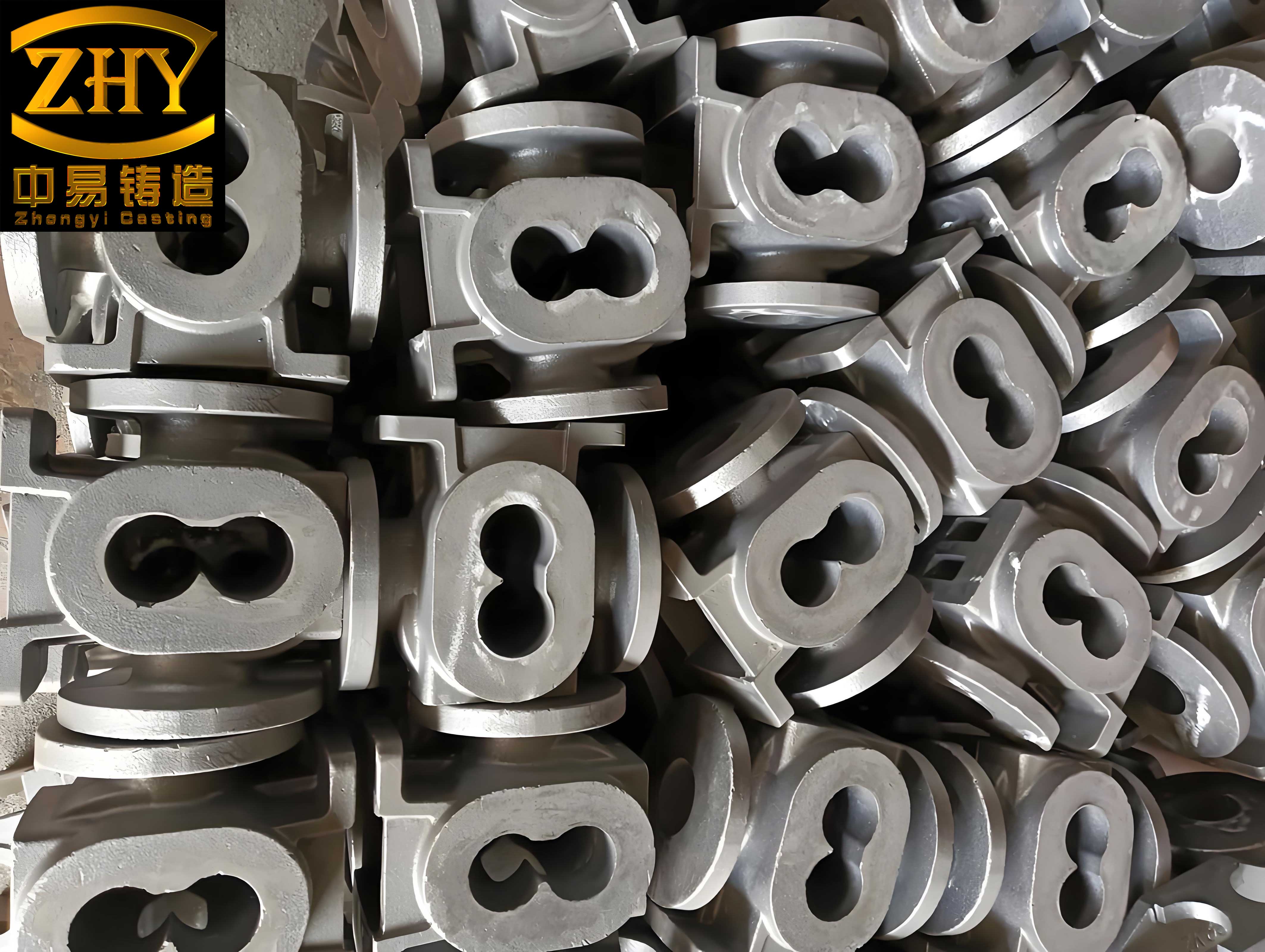
The initial casting process for the nodular cast iron gearbox housing involved a top-gating system, which we later identified as a root cause of defects. The pattern assembly included a 4 mm machining allowance on the end faces, with pouring temperatures between 1,370°C and 1,440°C, furnace tapping temperatures of 1,580–1,600°C, a negative pressure of -0.06 to -0.04 MPa, and a pressure holding time of 900 seconds. The chemical composition of the nodular cast iron, conforming to QT450-10 grade, is summarized in Table 1. Although the mechanical properties from Y-block samples met specifications, with nodularity grades of 2–3, the actual castings exhibited wrinkles on the end surfaces and shrinkage cavities at geometric hot spots, such as around bolt holes and thick sections.
| Element | C | Si | Mn | P | S | Mg | RE |
|---|---|---|---|---|---|---|---|
| Content | 3.5–4.0 | 2.0–3.0 | ≤0.45 | ≤0.05 | ≤0.025 | 0.02–0.06 | 0.015–0.04 |
To understand the defect formation mechanisms, we analyzed the gating system and solidification behavior. For wrinkles, the top-gating design inadvertently created a mid-bottom filling pattern due to the housing’s geometry. The molten iron entered from the top, penetrated the thick upper section, and then flowed downward through thinner regions, leading to turbulent flow and cold zones where pattern decomposition products accumulated. These products, primarily carbonaceous residues from the foam, adhered to the metal surface, resulting in orange-peel-like wrinkles. The phenomenon can be modeled by considering the heat transfer and gas evolution dynamics. The rate of pattern decomposition \( R_d \) is given by:
$$ R_d = A e^{-E_a / (RT)} $$
where \( A \) is the pre-exponential factor, \( E_a \) is the activation energy, \( R \) is the gas constant, and \( T \) is the temperature. In turbulent flow, the residence time of metal in cold zones increases, allowing more carbon deposition. The carbon defect risk \( C_{risk} \) can be expressed as:
$$ C_{risk} = \int_0^t \left( \frac{\partial m_c}{\partial t} \right) dt $$
where \( m_c \) is the mass of carbonaceous byproducts, and \( t \) is time. For our initial process, simulations indicated high \( C_{risk} \) values at the top surfaces, correlating with observed wrinkles.
Regarding shrinkage cavities, nodular cast iron exhibits significant volumetric contraction during solidification due to its high carbon equivalent (CE), calculated as:
$$ CE = C + \frac{Si + P}{3} $$
For our composition, CE ranges from 4.2 to 4.5, promoting graphitization expansion but also liquid shrinkage. In geometric hot spots, such as the bolt hole regions with localized thickness increases, the modulus \( M \) (volume-to-surface area ratio) is high, delaying solidification and creating isolated liquid pools. The solidification time \( t_s \) for a spherical hot spot can be estimated using Chvorinov’s rule:
$$ t_s = B \left( \frac{V}{A} \right)^2 = B M^2 $$
where \( B \) is a mold constant, \( V \) is volume, and \( A \) is surface area. Without adequate feeding, shrinkage cavities form, as the liquid metal cannot compensate for the contraction. Our analysis confirmed that the original process lacked effective cooling or feeding mechanisms for these hot spots.
To address the wrinkle defect, we redesigned the gating system from top-gating to a bottom-gating configuration. This change aimed to ensure laminar filling, where metal rises steadily from the bottom, pushing decomposition products upward toward the machining allowances. The gating system calculations were based on hydrodynamic principles. The pouring time \( t_p \) is critical and was derived from:
$$ t_p = \frac{24S}{\sqrt{H}} $$
where \( S \) is the cross-sectional area of the sprue in cm², and \( H \) is the effective metallostatic head height in cm. For bottom-gating, the average head height \( H_{avg} \) is:
$$ H_{avg} = H – \frac{P^2}{2C} $$
with \( P \) as the pressure head and \( C \) as a constant. In our case, \( H_{avg} \) was calculated as 34 cm. The minimum ingate area \( A_{min} \) was determined using:
$$ A_{min} = \frac{W}{\rho \cdot v \cdot t_p} $$
where \( W \) is the casting weight (112 kg), \( \rho \) is the density of nodular cast iron (approximately 7.1 g/cm³), and \( v \) is the flow velocity. Simplifying with empirical formulas, we obtained \( A_{min} = 3.46 \, \text{cm}^2 \). Considering LFC requirements, we designed a central sprue with four ingates, each with dimensions of \( 7 \times 40 \, \text{mm} \), giving a total area of 11.2–12.8 cm². The sprue height was set to 480 mm with a pressure head of 200 mm. This bottom-gating system promoted sequential filling, reducing turbulence and carbon entrapment.
The validation involved producing 2,000 castings with the new design. Results showed a complete elimination of wrinkles, as depicted in comparative images. The surface quality met specifications, confirming that bottom-gating effectively minimized cold zones and carbon defects. We further analyzed the filling behavior using computational fluid dynamics (CFD) simulations, which demonstrated a smooth velocity gradient and reduced vortex formation. The improvement can be quantified by the Reynolds number \( Re \):
$$ Re = \frac{\rho v D}{\mu} $$
where \( D \) is the hydraulic diameter and \( \mu \) is the dynamic viscosity. For the original top-gating, \( Re \) exceeded 4,000 in regions, indicating turbulence, while for bottom-gating, \( Re \) remained below 2,000, ensuring laminar flow.
For shrinkage cavities, traditional methods like risers or chills were deemed unsuitable due to lower yield and practicality issues in LFC. Instead, we developed a heat dissipation process, involving the attachment of foam sheets (heat dissipation plates) to the geometric hot spots. These plates, made of the same co-polymer material as the pattern, increase the surface area for heat transfer during solidification. Under negative pressure, cold air infiltrates the sand mold, flowing around the plates and casting, enhancing convective cooling. The heat flux \( q \) from the casting to the environment can be expressed as:
$$ q = h_c (T_c – T_\infty) + \sigma \epsilon (T_c^4 – T_\infty^4) $$
where \( h_c \) is the convective heat transfer coefficient, \( T_c \) is the casting surface temperature, \( T_\infty \) is the ambient temperature, \( \sigma \) is the Stefan-Boltzmann constant, and \( \epsilon \) is the emissivity. The plates amplify \( h_c \) by creating micro-channels for air flow. The modified modulus \( M’ \) with plates becomes:
$$ M’ = \frac{V}{A + A_p} $$
where \( A_p \) is the additional surface area from plates. For the bolt hole regions, we attached 12 plates, each sized \( 50 \times 30 \times 7 \, \text{mm} \), increasing the surface area by approximately 30%. This reduced the local solidification time, promoting directional solidification toward the feeding sources.
The heat dissipation process was tested on the same production batch. After machining, the bolt hole areas showed no shrinkage cavities, as verified by non-destructive testing. We conducted microstructural analysis on samples from both original and optimized processes, as summarized in Table 2. The nodular cast iron from the optimized process exhibited finer graphite nodules and reduced porosity, enhancing mechanical properties.
| Parameter | Original Process | Optimized Process |
|---|---|---|
| Graphite Nodule Count (per mm²) | 120–150 | 180–220 |
| Nodularity Grade | 2–3 | 1–2 |
| Porosity Area (%) | 0.5–1.0 | < 0.1 |
| Yield Strength (MPa) | 310–330 | 340–360 |
| Tensile Strength (MPa) | 450–470 | 480–500 |
| Elongation (%) | 10–12 | 12–15 |
The effectiveness of the heat dissipation plates stems from the enhanced cooling rate \( \dot{T} \), which can be derived from the heat balance equation:
$$ \dot{T} = \frac{q}{\rho c_p V} $$
where \( c_p \) is the specific heat capacity. By increasing \( q \) through the plates, \( \dot{T} \) rises, shifting the solidification front and minimizing shrinkage. We also modeled the temperature distribution using finite element analysis (FEA), showing that the plates reduced the temperature gradient in hot spots by up to 40%, facilitating better feeding from adjacent sections.
In discussing broader implications, our approach highlights the adaptability of LFC for nodular cast iron components. The bottom-gating system not only resolves wrinkles but also improves metal yield by eliminating unnecessary risers. Similarly, the heat dissipation process offers a cost-effective alternative to chills, without complicating pattern assembly or reducing yield. For industries producing heavy-section nodular cast iron parts, such as in automotive or machinery sectors, these optimizations can lead to significant quality and economic benefits. Moreover, the principles can be extended to other alloy systems prone to shrinkage or carbon defects in LFC.
Further research could explore the optimal design of heat dissipation plates, perhaps using conductive materials or varying geometries to maximize cooling efficiency. Additionally, integrating real-time monitoring during pouring could help adjust negative pressure or pouring speed dynamically, further minimizing defects. The interplay between foam material properties and metal chemistry also warrants study, especially for high-carbon nodular cast iron grades where carbon pickup is a concern.
In conclusion, through systematic process refinements, we successfully eliminated wrinkles and shrinkage cavities in nodular cast iron gearbox housings produced by lost foam casting. The bottom-gating system ensured laminar filling, preventing carbonaceous deposits, while the innovative heat dissipation plates mitigated geometric hot spots by enhancing cooling rates. Both solutions were validated through large-scale production, demonstrating robustness and practicality. This work underscores the importance of tailored gating and cooling strategies in LFC, particularly for nodular cast iron applications demanding high integrity. Future endeavors will focus on automating these techniques and applying them to other complex castings, further advancing the capabilities of lost foam casting for nodular cast iron components.