
In my extensive experience with advanced casting techniques, the V-process, or vacuum molding process, has proven to be a highly effective method for producing large-scale spheroidal graphite cast iron components. These spheroidal graphite cast iron castings are critical in heavy machinery, such as loaders, where they must meet stringent dimensional, mechanical, and metallurgical requirements. This article delves into the comprehensive approach I adopted to manufacture a large backseat casting for a loader using spheroidal graphite cast iron, addressing inherent challenges like mold wall movement, shrinkage defects, and dimensional deviations. Through meticulous design, process optimization, and innovative solutions, we achieved consistent quality in these spheroidal graphite cast iron parts, highlighting the versatility of the V-process.
The backseat casting, made of spheroidal graphite cast iron with a grade equivalent to QT400-18, presented a significant undertaking due to its substantial size and complex U-shaped geometry. With dimensions of approximately 3,195.6 mm × 1,352.55 mm × 993.78 mm and a weight of 5,906 kg, the casting featured an average wall thickness of 120 mm and a maximum of 203 mm. Such thick sections in spheroidal graphite cast iron are prone to issues like graphite flotation, shrinkage porosity, and deformation, exacerbated by the V-process’s dynamic vacuum conditions. The technical specifications demanded a fully ferritic matrix, spheroidal graphite of grade 3, tensile strength of at least 400 MPa, elongation of 18%, and hardness between 149–187 HB. Meeting these for spheroidal graphite cast iron required a holistic strategy encompassing tooling design, gating and risering, melting treatment, and process control.
To systematically outline the key parameters, I have compiled the casting’s primary requirements in Table 1. This table underscores the critical benchmarks for spheroidal graphite cast iron in this application.
| Parameter | Specification |
|---|---|
| Material | Spheroidal Graphite Cast Iron (QT400-18) |
| Dimensions | 3,195.6 mm × 1,352.55 mm × 993.78 mm |
| Weight | 5,906 kg |
| Average Wall Thickness | 120 mm |
| Maximum Wall Thickness | 203 mm |
| Matrix Structure | Ferrite |
| Graphite Spheroidization Grade | 3 |
| Tensile Strength | ≥ 400 MPa |
| Elongation | ≥ 18% |
| Hardness | 149–187 HB |
The core challenge lay in adapting the V-process for such a massive spheroidal graphite cast iron casting. In the V-process, a vacuum is applied to a mold filled with dry, unbonded sand, which is sealed with a plastic film. While excellent for surface finish and environmental benefits, the process can suffer from reduced mold stiffness due to vacuum fluctuations, leading to mold wall movement during solidification. For spheroidal graphite cast iron, which undergoes significant graphite expansion, this can result in shrinkage cavities, porosity, and weight variations. Additionally, the U-shaped geometry heightened risks of warping, and the large volume of molten iron—nearly 8 tons—posed difficulties in spheroidization treatment without degradation. To overcome these, I designed a tailored process from scratch.
First, the tooling and equipment were customized. A dedicated V-process sandbox was engineered with dimensions of 4,000 mm × 2,260 mm × 650/950 mm. Its structure incorporated dense, hollow ribs connected to side vacuum chambers, with ventilation screens on the ribs to ensure uniform vacuum distribution. The rib height was contoured to follow the pattern shape, maintaining a 150–200 mm sand cover to stabilize mold rigidity. This design mitigated vacuum-induced variability, crucial for controlling the solidification of spheroidal graphite cast iron. For molten metal handling, two 3-ton ladles were used for spheroidizing treatment, which were then transferred to an 8-ton ladle for pouring, addressing the capacity limitations.
The gating and risering system was meticulously planned. A flat parting surface was chosen, with the entire casting shape formed in the drag half to minimize mismatch and finishing marks. The cope side employed sand stacking for the U-shaped sides, facilitating cleanup. A semi-open gating system was adopted to ensure smooth, rapid filling, with a ratio designed to minimize turbulence and oxidation. The gating ratio can be expressed as:
$$ \sum F_{\text{sprue}} : \sum F_{\text{runner}} : \sum F_{\text{ingate}} = 1 : 0.8 : 1.5 $$
where \( \sum F \) denotes the total cross-sectional areas. This ratio promoted a calm flow essential for spheroidal graphite cast iron quality. For feeding, two inverted bottle-shaped open risers, each 200 mm in diameter and 500 mm high, were placed at the thick sections at both ends, with neck dimensions of φ80 mm × 60 mm. During pouring, exothermic compounds were added to these risers to enhance their efficiency. Additionally, nine vent risers of φ60 mm were strategically located to aid degassing. The overall layout is summarized in Table 2, highlighting the feeding design parameters.
| Component | Type | Dimensions | Quantity | Purpose |
|---|---|---|---|---|
| Main Riser | Inverted Bottle Open | φ200 mm × 500 mm | 2 | Feed thick sections |
| Riser Neck | Cylindrical | φ80 mm × 60 mm | 2 | Control feed path |
| Vent Riser | Cylindrical | φ60 mm | 9 | Exhaust gases |
| Gating System | Semi-open | Ratio 1:0.8:1.5 | 1 set | Ensure smooth filling |
The pattern was fabricated from wood using 5-axis CNC machining for precision. Due to size constraints, it was made in two halves and joined, ensuring dimensional accuracy and surface smoothness. Temporary ties were added across the U-opening to counteract cooling deformation, which were later removed post-casting. This attention to pattern detail was vital for the dimensional integrity of the spheroidal graphite cast iron casting.
Melting and treatment processes were rigorously controlled. A 12.5-ton induction furnace melted the base iron, targeting a composition that would yield the desired spheroidal graphite cast iron after treatment. The base iron chemistry aimed for: carbon 3.6–3.7%, silicon 1.5–1.6%, manganese 0.2–0.3%, phosphorus below 0.04%, and sulfur below 0.03%. To manage the large volume, spheroidization was conducted in three batches of 2.6 tons each in 3-ton ladles using a sandwich method with 3-8 grade spheroidizer (40 kg per batch) and 75% ferrosilicon inoculant (21 kg per batch), covered with iron plates to promote reaction. This ensured a final composition with silicon around 2.8%, magnesium 0.04%, and rare earths 0.03%, optimal for spheroidal graphite formation. The treated iron was combined into an 8-ton ladle, and during pouring, a stream inoculation with 0.1% Incoude900 was applied to prevent fade and enhance graphite spheroidization. Pouring temperature was maintained at 1,320–1,340°C over 4.5–5 minutes, with exothermic additions to the risers mid-pour. The chemical transitions are captured in Table 3, showing the evolution from base iron to final spheroidal graphite cast iron.
| Element | Base Iron (wt%) | After Treatment (wt%) | Role in Spheroidal Graphite Cast Iron |
|---|---|---|---|
| Carbon (C) | 3.6–3.7 | 3.4–3.5 | Promotes graphite nucleation, affects fluidity |
| Silicon (Si) | 1.5–1.6 | 2.7–2.9 | Ferritizer, enhances graphitization |
| Manganese (Mn) | 0.2–0.3 | 0.2–0.3 | Strengthens but can segregate; kept low |
| Phosphorus (P) | < 0.04 | < 0.04 | Impurity; minimized for toughness |
| Sulfur (S) | < 0.03 | < 0.02 | Interferes with spheroidization; reduced |
| Magnesium (Mg) | – | 0.03–0.05 | Key spheroidizing agent |
| Rare Earths (RE) | – | 0.02–0.04 | Aids spheroidization, counteracts impurities |
Molding involved the custom sandbox, with sand compaction time around 2.5 minutes to achieve a mold hardness above 90. The vacuum level was kept steady above 0.06 MPa (abs. ~0.04 MPa gauge) to sustain mold rigidity during the critical solidification phase of the spheroidal graphite cast iron. This high stiffness resisted the graphite expansion pressure, reducing shrinkage tendencies. Furthermore, localized cooling was applied to thicker regions to promote directional solidification, a principle governed by the Chvorinov’s rule for solidification time \( t \):
$$ t = k \left( \frac{V}{A} \right)^2 $$
where \( V \) is volume, \( A \) is surface area, and \( k \) is a mold constant. By manipulating cooling rates, we ensured that the thicker sections solidified later, aided by the risers.
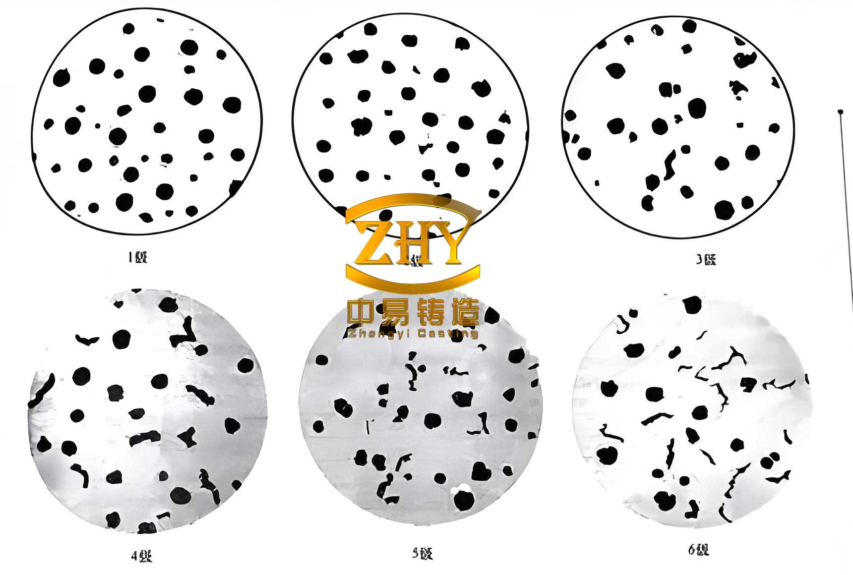
The results from batch production were highly satisfactory. The spheroidal graphite cast iron castings exhibited no macroscopic shrinkage cavities or porosity, with sound internal structure confirmed by ultrasonic testing. Surface finish was excellent, and dimensional accuracy met tolerances within ±2 mm, with no warping due to the ties and controlled cooling. Mechanical testing of separately cast keel blocks yielded tensile strength of 490 MPa, elongation of 19%, and hardness of 180 HB, exceeding specifications. Metallographic analysis showed graphite spheroidization grade 3 and ferritic matrix, as required. These outcomes validate the process design for spheroidal graphite cast iron in V-process casting. A visual representation of the spheroidal graphite cast iron microstructure, highlighting the spherical graphite nodules in a ferritic matrix, is provided below to illustrate the typical material quality achieved.
To quantify the benefits, compared to traditional green sand casting, the V-process for these spheroidal graphite cast iron components reduced molding material costs by over 60% and saved more than 4% in metal usage through improved yield and less machining allowance. Productivity increased due to faster mold preparation and lower labor intensity, while working conditions were cleaner. These advantages make the V-process a compelling choice for large spheroidal graphite cast iron castings.
From a metallurgical perspective, the behavior of spheroidal graphite cast iron during solidification is complex. The graphite expansion pressure \( P_{exp} \) can be approximated as:
$$ P_{exp} = \alpha \cdot \Delta V_{gr} \cdot E $$
where \( \alpha \) is a coefficient related to graphite volume fraction, \( \Delta V_{gr} \) is the volume change due to graphite precipitation, and \( E \) is the modulus of the mold. In the V-process, maintaining high and stable \( E \) via vacuum control is essential to counteract \( P_{exp} \) and prevent mold wall movement. Our sandbox design and vacuum management achieved this, ensuring dimensional consistency in the spheroidal graphite cast iron casting.
Moreover, the spheroidization and inoculation kinetics are critical. The efficiency of magnesium recovery \( \eta_{Mg} \) in the treatment can be modeled as:
$$ \eta_{Mg} = \frac{[Mg]_{final}}{[Mg]_{added}} \times 100\% $$
which typically ranges 40–60% for冲入法 (sandwich method). By using multiple small ladles, we optimized \( \eta_{Mg} \) to around 50%, ensuring sufficient residual magnesium for spheroidization without excessive dross. Post-inoculation with Incoude900, rich in strontium and barium, enhanced graphite nucleation sites, crucial for the thick sections of spheroidal graphite cast iron to avoid chilling and carbide formation.
In terms of process optimization, simulation software was employed to visualize filling and solidification. The results guided modifications like riser placement and cooling rates. For instance, the feeding efficiency \( \eta_{feed} \) of a riser can be expressed as:
$$ \eta_{feed} = \frac{V_{feed}}{V_{riser}} \times 100\% $$
where \( V_{feed} \) is the volume of metal fed to the casting, and \( V_{riser} \) is the riser volume. With exothermic aids, \( \eta_{feed} \) increased from an estimated 14% to over 20%, significantly reducing shrinkage risk in the spheroidal graphite cast iron.
The success of this project underscores several key principles for producing large spheroidal graphite cast iron castings via V-process. First, custom tooling with enhanced vacuum uniformity is paramount to stabilize mold stiffness. Second, a balanced gating system coupled with exothermic risers addresses feeding challenges. Third, meticulous control of melting, spheroidization, and inoculation—tailored to the massive volume—preserves the metallurgical quality of spheroidal graphite cast iron. Fourth, temporary ties and controlled cooling mitigate geometric distortions. These elements, combined with advanced monitoring, ensure that spheroidal graphite cast iron components meet rigorous standards consistently.
Looking broader, the V-process offers environmental and economic gains for spheroidal graphite cast iron foundries. The dry sand is reusable with minimal loss, and no binders reduce emissions. However, it demands precise vacuum control and specialized equipment, which may limit its adoption for smaller batches. For high-volume, large castings like loader backseats, it is highly advantageous.
In conclusion, through integrated design and process innovation, we have demonstrated that the V-process is viable for manufacturing large, thick-walled spheroidal graphite cast iron castings with superior quality. The strategies developed—from tailored sandboxes to optimized metallurgy—effectively countered defects like shrinkage and deformation, yielding spheroidal graphite cast iron parts that excel mechanically and dimensionally. This experience reinforces that understanding the interplay between process parameters and material behavior is crucial for advancing spheroidal graphite cast iron applications in demanding sectors. As foundries continue to push size and performance limits, such approaches will be instrumental in harnessing the full potential of spheroidal graphite cast iron.