
In the field of metal casting, the production of semi-enclosed casting parts presents unique challenges due to their structural complexity, thin and uneven walls, and internal cavities. These casting parts, often serving as critical components in machinery for bearing loads or containment, require precise manufacturing techniques to ensure quality and performance. Traditional sand casting methods, while common, involve complex processes such as core-making, leading to higher costs and longer production cycles. As a result, there has been a significant shift towards lost foam casting, a technology that has matured globally for materials like cast iron, steel, and aluminum alloys, with rapid innovations in automotive, aerospace, and alloy production sectors. Lost foam casting offers advantages for producing intricate casting parts, especially in small batches, by simplifying processes, reducing environmental impact, and enabling near-net-shape formation without parting lines or mold removal. This article, based on our practical experience, delves into the technical aspects of lost foam casting for semi-enclosed casting parts, focusing on process optimization to address common defects like collapse and expansion, thereby enhancing the yield and quality of these essential casting parts.
Our exploration begins with an overview of the lost foam casting process as applied to semi-enclosed casting parts. The key to success lies in mastering four critical elements: the foam pattern, coating, molding, and pouring methodology. Each step must be meticulously controlled to avoid defects that can compromise the integrity of the casting parts. For instance, the foam pattern must have uniform density and proper aging to prevent deformation; the coating must provide adequate strength, permeability, and refractoriness; the molding process must ensure tight compaction and balanced vacuum pressure; and the pouring technique must facilitate smooth metal flow while minimizing turbulence. Initially, our production yield for such casting parts was only around 40%, primarily due to issues related to inadequate vacuum formation within the internal cavities of semi-enclosed structures. This prompted us to investigate and implement improvements, particularly in mold setup and vacuum system design, which are detailed in the following sections.
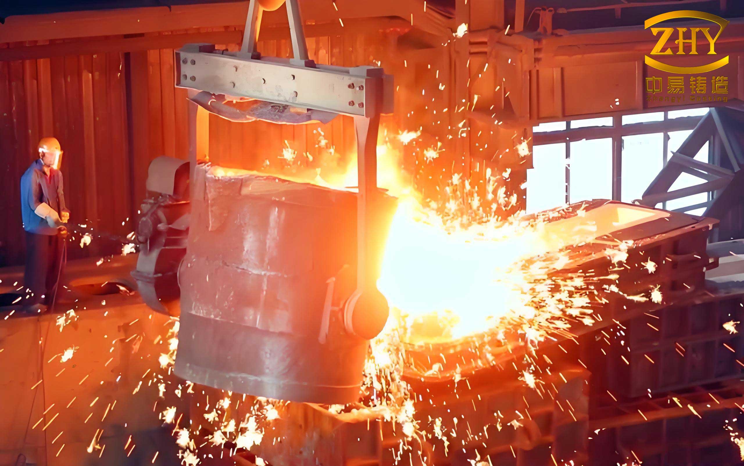
The lost foam casting process for semi-enclosed casting parts involves several sequential steps, each with specific parameters that influence the final outcome. We start with pattern making, using expandable polystyrene (EPS) foam boards with a density of 10 kg/m³. The patterns for the casting parts and the gating system are manually cut and assembled, ensuring seamless joints and smooth surfaces. Any imperfections, such as gaps or burns from cutting, are repaired with specialized tools and adhesives. After assembly, the patterns are dried to reduce moisture content below 0.8%, which is crucial to prevent gas generation during pouring that could lead to defects in the casting parts. The gating system is designed to facilitate gradual filling and minimize turbulence; a typical layout includes sprue, runners, and risers, as illustrated in process diagrams. For coating, we use water-based refractory coatings, mixed to a specific viscosity and applied in multiple layers—three coats for the main pattern and four for the gating system—with careful drying between coats to avoid distortion. The drying parameters are summarized in Table 1, highlighting the time and temperature controls essential for achieving a uniform, crack-free coating on the casting parts patterns.
| Process Step | First Coat Drying Time (h) | First Coat Drying Temperature (°C) | Second Coat Drying Time (h) | Second Coat Drying Temperature (°C) | Third Coat Drying Time (h) | Third Coat Drying Temperature (°C) | Additional Notes |
|---|---|---|---|---|---|---|---|
| Semi-enclosed Casting Parts | 20 | 35–45 | 24 | 40–50 | 26 | 45–50 | Re-coat corners and angles; ensure smooth, even flow |
Melting and alloy preparation are critical for producing high-quality casting parts. We use raw materials such as carbon steel scrap and plates, carefully selected to control chemical composition. The melting process is conducted in electric furnaces, starting with preheating at low power and gradually adding larger charges at higher power. Slag-forming agents are introduced to cover the molten metal, preventing oxidation. Before tapping, the slag is thoroughly removed, and the melt is sampled for chemical analysis to meet specifications, as shown in Table 2 for typical steel casting parts. The target pouring temperature ranges from 1,550 to 1,600°C, with a tapping temperature around 1,650°C to account for cooling during handling. This ensures proper fluidity for filling the intricate cavities of semi-enclosed casting parts without premature solidification.
| Element | C | Si | Mn | P | S | Cr | Ni | Mo | Cu | V |
|---|---|---|---|---|---|---|---|---|---|---|
| Content | ≤0.25 | ≤0.40 | ≤1.00 | ≤0.035 | ≤0.035 | ≤0.40 | ≤0.35 | ≤0.15 | ≤0.05 | ≤0.06 |
Molding is a pivotal stage where the coated pattern is embedded in unbonded sand within a flask. For semi-enclosed casting parts, we adopt a one-pattern-per-flask approach. The pattern is positioned in the flask, and sand is added in layers while vibrating on a compaction table to ensure tight packing around the complex geometry. The vibration frequency is maintained at 40–50 Hz for a total time exceeding 600 seconds, with intermediate pauses to add sand and prevent voids. However, due to the enclosed nature of these casting parts, achieving uniform sand compaction and vacuum distribution inside the internal cavities is challenging. Initially, we placed the pattern horizontally, but this led to inadequate sand flow into cavities, resulting in loose areas that contributed to defects. The pouring process involves careful control of vacuum pressure; the flask is connected to a vacuum system to stabilize the sand mold and remove gases from foam decomposition. Pouring is completed within 5 minutes, followed by a holding period of 10 minutes under vacuum to allow solidification and pressure equalization. Despite these measures, we observed recurring defects in the casting parts, such as collapse (sand crushing), expansion (swelling of the mold), and dimensional distortion, which we analyzed systematically to identify root causes.
The defects in semi-enclosed casting parts primarily stem from imbalances in vacuum pressure and sand compaction. For collapse and expansion defects, the key factors include insufficient vacuum within internal cavities, uneven sand density, and excessive thermal pressures during pouring. Mathematically, the pressure difference (ΔP) across the mold wall can be expressed as:
$$ \Delta P = P_{\text{internal}} – P_{\text{external}} $$
where \( P_{\text{internal}} \) is the pressure inside the cavity due to gas generation from foam decomposition and metal advancement, and \( P_{\text{external}} \) is the vacuum pressure applied externally. If \( \Delta P \) becomes too positive (i.e., internal pressure exceeds external), it can cause expansion or swelling of the mold; if too negative, it may lead to collapse due to inadequate support. For semi-enclosed casting parts, the internal cavity often lacks direct vacuum connection, leading to \( P_{\text{internal}} \approx P_{\text{atm}} \) (atmospheric pressure) or higher from gases, while \( P_{\text{external}} \) is reduced by the vacuum pump. This imbalance can be quantified using the ideal gas law and flow dynamics. For instance, the gas generation rate \( \dot{V} \) from foam decomposition is proportional to the metal front velocity \( v_m \) and pattern density \( \rho_f \):
$$ \dot{V} = k \cdot \rho_f \cdot v_m $$
where \( k \) is a constant dependent on foam material. If the vacuum system cannot evacuate this gas quickly enough, pressure builds up, increasing \( P_{\text{internal}} \). Simultaneously, the sand’s ability to resist deformation is governed by its compactness, which can be characterized by the sand’s shear strength \( \tau \), related to vibration energy and packing density. We observed that defects often occurred in casting parts with thin walls and deep cavities, where sand flow was restricted. Table 3 summarizes the defect types and their measured dimensional deviations in initial trials, highlighting the impact on casting parts quality.
| Defect Type | Affected Dimension | Nominal Size (mm) | Measured Size (mm) | Deviation (mm) | Impact on Casting Parts |
|---|---|---|---|---|---|
| Collapse | Internal cavity width | 900 | 870 | -30 | Reduced functionality, potential leakage |
| Expansion | Overall length | 1,400 | 1,386 | -14 | Dimensional inaccuracy, machining required |
| Distortion | Internal cavity length | 1,320 | 1,308 | -12 | Wall thinning, stress concentrations |
| Expansion | Overall width | 980 | 954 | -36 | Poor fit-up in assemblies |
To address these issues, we focused on optimizing the molding and vacuum systems. First, we modified the pattern orientation during molding. Instead of horizontal placement, we tilted the pattern so that the open face of the semi-enclosed casting parts was inclined at an angle to facilitate sand flow into cavities. After testing various angles, we found that 45° tilt provided the best compromise: it allowed sand to naturally fill gaps without excessive manual intervention, ensured uniform compaction, and minimized dead zones where sand could be loose. The tilt angle \( \theta \) influences the gravitational component aiding sand flow, described by:
$$ F_g = \rho_s \cdot g \cdot V \cdot \sin(\theta) $$
where \( \rho_s \) is sand density, \( g \) is gravity, and \( V \) is the volume of sand. At \( \theta = 45^\circ \), \( \sin(45^\circ) \approx 0.707 \), providing sufficient force for sand to penetrate cavities while maintaining pattern stability. Angles below 30° resulted in inadequate filling, and above 60° caused bridging and uneven compaction in lower regions of the casting parts.
Second, we introduced an external negative pressure tube to balance vacuum distribution inside the cavities of semi-enclosed casting parts. This tube, made of perforated steel with a diameter of 150 mm, is inserted into the internal cavity during molding and connected to the main vacuum system via hoses. The tube is wrapped with wire mesh and has small holes (2 mm diameter) spaced 15 mm horizontally and 10 mm vertically to allow gas evacuation without sand ingress. The design ensures that during pouring, both external and internal regions of the mold are under similar vacuum levels, reducing \( \Delta P \). The vacuum pressure \( P_v \) as a function of flow rate \( Q \) and tube geometry can be approximated by Darcy’s law for porous media:
$$ Q = \frac{A \cdot k}{\mu} \cdot \frac{\Delta P}{L} $$
where \( A \) is the cross-sectional area, \( k \) is permeability, \( \mu \) is gas viscosity, and \( L \) is length. By integrating this tube, we effectively extended the vacuum network into the core of the casting parts, promoting uniform degassing and stabilization. This approach is particularly beneficial for large or complex casting parts where internal volumes are significant.
The implementation of these improvements yielded substantial gains in the quality of casting parts. We conducted 12 production trials, each with 4 casting parts, using the 45° tilt and external vacuum tube. The results, summarized in Table 4, show a dramatic reduction in defects. Collapse and expansion defects dropped from over 50% occurrence to less than 10%, with overall yield increasing to 90%. The external tube proved reusable and easy to integrate, adding minimal cost while significantly enhancing process reliability for semi-enclosed casting parts. Furthermore, dimensional consistency improved, as evidenced by closer adherence to nominal sizes, reducing post-casting machining and rework.
| Metric | Before Optimization | After Optimization | Improvement | Impact on Casting Parts Production |
|---|---|---|---|---|
| Collapse/Expansion Defect Rate | ~60% | 6% (3 out of 48 pieces) | 90% reduction | Higher yield, less scrap |
| Dimensional Deviation (avg.) | ±20 mm | ±5 mm | 75% reduction | Better accuracy, reduced machining |
| Overall Yield | 40% | 90% | 125% increase | More efficient use of materials |
| Process Stability | Variable vacuum, frequent defects | Consistent vacuum, fewer issues | Enhanced control | Predictable quality for casting parts |
In conclusion, the lost foam casting process for semi-enclosed casting parts requires careful attention to vacuum balance and sand compaction. By tilting the pattern at 45° during molding and employing an external negative pressure tube, we effectively addressed the root causes of collapse and expansion defects. These modifications ensure uniform sand filling and equalized pressure distribution, leading to higher yields and better dimensional accuracy for such casting parts. Our practice demonstrates that with targeted improvements, lost foam casting can reliably produce complex semi-enclosed casting parts, leveraging its advantages in simplicity and flexibility. Future work may explore advanced simulation models to optimize tilt angles and tube designs for specific casting parts geometries, further pushing the boundaries of this versatile technology. Ultimately, the goal is to consistently deliver high-integrity casting parts that meet the demanding requirements of modern industrial applications.
Throughout this study, we emphasize that the success in producing semi-enclosed casting parts hinges on a holistic approach—integrating pattern design, coating, molding, and vacuum control. Each step interplays to influence the final quality of the casting parts. For instance, the coating thickness must be optimized to withstand thermal shocks without cracking, which can be expressed as a function of thermal conductivity \( \lambda \) and coefficient of thermal expansion \( \alpha \):
$$ \sigma_{\text{thermal}} = E \cdot \alpha \cdot \Delta T $$
where \( \sigma_{\text{thermal}} \) is the thermal stress, \( E \) is Young’s modulus, and \( \Delta T \) is the temperature difference during pouring. By controlling these parameters, we minimize coating failure that could lead to sand penetration defects in casting parts. Similarly, the pouring rate must be synchronized with vacuum draw to maintain a stable metal front; too fast pouring can cause turbulence, while too slow can lead to premature solidification in thin sections of casting parts. We use empirical formulas to estimate the optimal pouring time \( t_p \) based on casting parts volume \( V_c \) and gating area \( A_g \):
$$ t_p = \frac{V_c}{A_g \cdot v_c} $$
where \( v_c \) is the critical velocity to avoid mold erosion. These technical nuances underscore the importance of a detailed, science-driven approach in manufacturing casting parts via lost foam casting.
In summary, our research and practice highlight that semi-enclosed casting parts can be produced efficiently with lost foam casting by addressing vacuum and compaction challenges. The key takeaways include the benefits of tilted molding at 45° and the use of external vacuum tubes to balance internal pressures. These strategies not only improve yield but also enhance the mechanical properties and surface finish of casting parts, making lost foam casting a competitive choice for complex components. As industries continue to demand lighter, stronger, and more intricate casting parts, further innovations in this area will undoubtedly emerge, solidifying lost foam casting’s role in advanced manufacturing.