
Gas turbines are known as the “crown jewel” of the equipment manufacturing industry and are the core power equipment of the 21st century. According to its structural form, it is divided into heavy gas turbine, light gas turbine and micro gas turbine. Due to many reasons, there is still a big gap between China’s gas turbines and the international advanced level, and a real industry has not yet been formed. The gas turbine unit consists of compressor, combustion chamber, turbine, control and auxiliary systems. The compressor, combustion chamber and gas turbine are the three main components of a gas turbine. Gas turbines are divided into E, F and H classes according to the combustion chamber temperature, and the F-class combustion temperature reaches more than 1200°C. Compared with the traditional power station large steel castings, the design structure and casting process of F-class heavy-duty gas turbine shell castings are completely new manufacturing technology, the casting size is large, the wall is thin, the structure is complex, due to the use of working conditions on the internal quality and dimensional accuracy of the casting is very demanding, casting production is difficult. This paper combines the structural characteristics and quality requirements of combustion chamber shell products, and performs virtual simulation through MAGMA simulation, according to the production and manufacturing conditions And the process control requires the combustion chamber shell casting process to be studied, a reasonable casting process scheme is designed, and finally a casting product with qualified quality is produced.
1 Shell casting structure and quality requirements
1.1 Casting structure
Combustion chamber shell rough machined delivery castings with contour dimensions of 4140 mm × 2075 mm × 1348 mm, main wall thickness 45 mm, wall thickness tolerance required 0 ~ + 8 mm, maximum wall thickness 85 mm,
Minimum wall thickness 40 mm. The casting is divided into two semi-conical structures from the middle flange, the lower part has a prescription maintenance window, the upper part of the 12 round burner holes are evenly distributed, the shape and structure are complex, it belongs to a large thin-walled complex steel casting, easy to deform during the production process, the structure is shown in Figure 1.
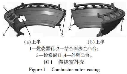
As shown in Figure 1, the combustion chamber housing is divided into two castings, the upper half of the housing and the lower half of the housing. The main rotation structure of the upper and lower parts is the same, but the difference lies in the staggered distribution of the boss position at the flange position of the upper and lower joint surfaces, and the structure of multiple boss positions distributed on the outer wall of the slewing is different.
Table 1 Chemical composition requirements (mass fraction, %)
| C | Si | Mn | P | S | Cr | Mo | Ni | Cu | V | AL Ti Sn |
| 0. 20 ~ 0. 26 | ≤0. 40 | 0. 50 ~ 0. 80 | ≤0. 030 | ≤0. 020 | 11. 30 ~ 12. 20 | 1. 00 ~ 1. 20 | ≤1. 00 | ≤0. 30 | 0. 25 ~ 0. 35 | Report for informational purposes |
Table 2 Mechanical property requirements
| Test temperature/℃ | Rp0. 2 ∕MPa | Rm∕MPa | A∕% | KV2∕J |
| 20 | ≥540 | 740 ~ 880 | ≥15 | ≥27 |
| 550 | ≥290 | Report for informational purposes |
1.2Castings quality requirements
The combustion chamber shell castings are made of GX23CrMoV12⁃1 heat-resistant steel [5] developed on the basis of Cr12 stainless steel, which implements the EN 10213⁃2007 “Technical Conditions for Pressure Bearing Steel Castings” standard, which is comparable to the ZG23Cr12MoV steel in GB/T 16253-2019 “Compression Steel Castings” [6]. The chemical composition and mechanical properties of the materials are shown in Tables 1 and 2.
After the combustion chamber shell casting of the heavy-duty gas turbine is finished, a layer of high-temperature resistant material is installed on the surface, and the steam temperature in the casting reaches 1400 ~ 1500°C when the unit is running. Due to the casting body
Finally, many small holes must be processed to install ceramic heat insulation sheets, and there can be no shrinkage and inclusions inside the casting. Due to the high temperature and pressure of the casting working environment, this product has strict dimensional requirements.
The internal quality requirements of the products are also high: castings are 100% magnetic particle tested according to EN 1369 and quality class 2 is required; Castings are 100% penetrant tested according to EN 1371, quality level 2 is required; The castings are 100% sonicated according to EN 12680⁃ 2, quality class 2 + permissible limit value ESR (straight probe equivalent) 6mm, RT when UT inspection results cannot be judged.
2 Shell casting process design
2.1 Casting shrinkage scheme design
According to the process design principle of steel castings, the position of risers and cold iron is reasonably determined, so that the casting in each riser of the complement of the norm A good temperature gradient is formed in the enclosure, so that it can be sequentially solidified from the end area of the shrinkage to the riser to obtain a dense and sound casting. The combustion chamber shell has a large size, complex shape structure, and a large-size thin-walled design with an equal wall thickness of 45 mm in the main rotating structure, from the design of the part structure, the part structure itself is not conducive to casting and shrinkage, and it is easy to deform. Since almost all of the casting body needs to be drilled, the internal quality of the casting is high, and there can be no shrinkage and inclusion. Its material grade is GX23CrMoV12⁃ 1, which belongs to high Cr martensitic heat-resistant steel, the flow performance of the material is poor, compared with low alloy materials, its shrinkage distance is short, the shrinkage effect is poor, and it is easy to produce shrinkage and shrinkage defects during the solidification process. Therefore, in the casting process design, it is necessary to combine the casting structure and material shrinkage performance to design the distribution and shrinkage of the riser. The riser distribution should be set according to its effective shrinking distance, and according to the structural characteristics of the shell product, it is necessary to use segments and partitions for compensation. In each riser shrinkage area, it is also necessary to fully consider the material shrinkage performance, and the casting structure is densely packed by increasing the temperature gradient of the solidification process from the end zone to the riser position to obtain a qualified product.
In the casting process design, according to the shell casting structure, it is divided into two sections from the bottom of the maintenance window, the lower section is divided into riser filling range according to the filling distance, and the dark riser is set; The above paragraph is based on The 12 circular burner holes are partitioned with risers at the top for retraction. Two riser distribution schemes are designed for the position structure of 12 circular burner holes in the upper section, and the scheme one is to set the riser in two circles according to the casting structure in the position of the inner ring flange on the top surface and the large flange on the outer side of the burner hole, as shown in Figure 2(a); Scheme 2: Spaced the burner holes by casting, a riser is provided at the location of the burner hole, as shown in Figure 2(b).
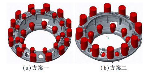
Figure 2 Riser distribution
Scheme 1 has a large number of risers compared with Scheme 2, and requires more steel water than Scheme 2, and the process calculation combined with MAGMA software solidification simulation adjustment is optimized, and the riser distribution mode of Scheme 2 is finally determined. The lower dark riser was adjusted from a spherical fiber riser to a heat preservation riser, and the position of the open riser table and the top flange was optimized. The design scheme after improving the shrinkage area, contraction gradient and meat increase subsidy of each riser is shown in Figure 3.
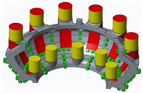
Figure 3 Riser distribution and shrinkage process scheme
The casting process design divides the lower section into 5 zones, each with a dark riser, and an external cooling partition is used between the risers. The upper section is divided into 6 zones, with a bright riser for each hole spaced by the circular burner hole. A 1:10 slope meat increase subsidy is set from the upper and lower partition areas at the bottom of the inner cavity maintenance window to increase the temperature gradient of each shrinkage area under the riser during the solidification process, and an external cooling partition is used between each filling zone to ensure the density inside the casting in the main area of the casting.
2.2Styling design
According to the casting structure, combined with the production of tooling aids and molding pouring conditions of our factory, using the method shown in Figure 4 and Figure 5, the upper and lower halves of the combustion chamber shell are connected and cast into a ring shape by increasing the cutting port of the joint surface flange, which can not only improve the production efficiency of molding, pouring and effectively prevent the deformation of castings.
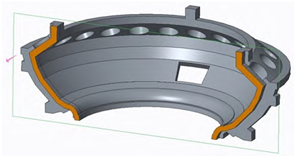
Figure 4 Illustration of the upper and lower half casting sections of the housing
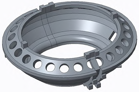
Figure 5 Illustration of the upper and lower half casting scheme of the shell
The middle flange is selected as the parting surface, the main core of the inner cavity is the overall structure, and the upper and lower half of the joint surface flange connects the cutting part to the lower core separately. The parting surface and core structure are shown in Fig. 6 and Figure 7.
2.3Size and crack risk control
For the large-size thin-walled structure of the combustion chamber shell, the casting process scheme design not only needs to consider the deformation caused by the inconsistency of cooling and shrinkage in various regions during the solidification process, but also considers the deformation of the casting during the heat treatment process in combination with the furnace loading method designed by the heat treatment process. Also targets high Cr martensitic heat-resistant steels
For problems with high tendency to hot cracking, effective precautions need to be taken for areas at high risk of thermal cracking in the MAGMA stress simulation results.
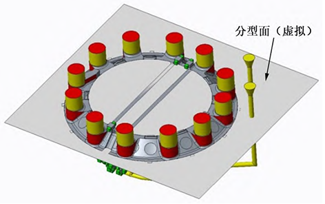
Figure 6 Parting surface
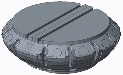
Figure 7 Schematic of the sand core structure
According to the production experience of similar semi-annular composite casting structure products in our factory and the wall thickness tolerance requirements of shell castings, a reasonable machining allowance and blank surface correction amount were selected, combined with the analysis of MAGMA stress simulation results, and selected 1. 8% scale. According to the heat treatment process, the upper and lower halves of the shell casting will be cut from the connection of the flange joint surface after the molding sand is cleaned, and the upper and lower halves will be heat treated with performance respectively. For defense After the separation of the casting, the semi-annular structure of the casting is deformed in the opening part during the heat treatment process, and the casting process sets the upper and lower layers of tension ribs in the opening direction according to the requirements of the heat treatment process. Furnace loading according to casting heat treatment In order to prevent the high temperature deformation of the shell during the heat treatment process, an anti-deformation triangular rib is set at the inflection point of the inner cavity of the middle flange. 4 circles of the service window with a large tendency to hot cracking shown in the simulation results The corners, anti-deformation ribs and the position of the mid-faceted flange increase the fillet to R120 mm. The external cooling of the partition on the wall thickness of all main bodies adopts round steel external cooling to prevent the occurrence of cracks between the external cooling.
2.4 Gating system design
The material GX23CrMoV12⁃ 1 of the combustion chamber shell casting is a high Cr martensitic heat-resistant cast steel with poor molten steel fluidity and easy to produce oxidative inclusions. Therefore, the pouring process needs to be smooth and fast, reducing the roll gas and slag inclusion during the pouring process. The process design is to ensure smooth filling and smooth exhaust, and the bottom-back pouring system is adopted. In order to reduce the turbulence of molten steel entering the cavity and improve the floating capacity of slag inclusion, the process specially designed the tangentially introduced bottom return water port to the boss to ensure smooth and rapid filling after the molten steel enters the cavity, combined with the actual production situation, a single package ⌀90 mm double-wrapped eye argon protection pouring is adopted. Gating system
The design is shown in Figure 8.
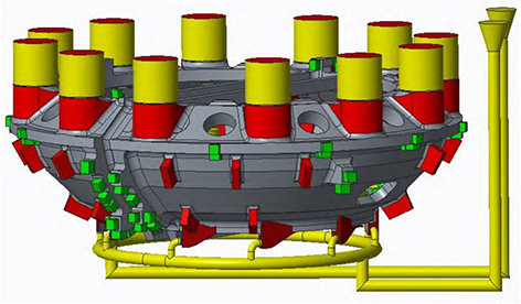
Figure 8 Distribution of the gating system
2.5 Analysis of solidification simulation results
The simulation results of the final process scheme crater and shrinkage reduction are shown in Figure 9 and Figure 10 by simulating the optimization scheme several times by simulating the optimization scheme by MAGMA software.
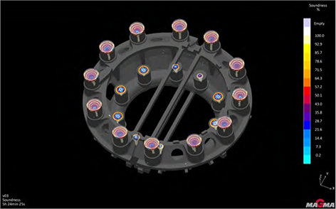
Figure 9 Shrink holes
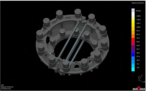
Figure 10 Shrinkage
The simulation results show that the shell casting body as a whole has no shrinkage defects. The niyama criterion is 0 for thin-walled castings based on the experience of MAGMA software applications. 3 ~ 0. 6 Conduct analysis. The niyama criterion is set to 0. 3 hours, the casting body is displayed without defects; The Niyama criterion is set to 0. At 6 o’clock, except for the riser and tension position castings, only the partial position of the external cooling partition is displayed with some defects. Based on the experience of using MAGMA software, the point-like niyama in the cold partition area of thin-walled castings shows no quality risk.
3 Production process control
In order to ensure the quality of castings, the model structure is reasonably divided, and the model is made by CNC machining to ensure the size of the model. After completion, the size of the model and core box passed three-dimensional inspection, all dimensions were qualified, and the deviation was within the tolerance of the model size. The molding adopts alkaline phenolic resin sand molding, and the surface of the cavity is brushed with water-based zirconin powder paint. Because the inner cavity structure of the casting is formed by the sand core, the core size needs to be strictly controlled during the molding core process, and the cavity size of the casting is ensured by auxiliary methods such as sample inspection in the molding. Large cone on the upper part of the casting The shape surface and upper box surface are easy to form pores, slag inclusions and other defects, and endoscopic inspection is used before pouring to remove impurities such as floating sand inside the cavity to ensure the cleanliness of the cavity.
4 Product quality status
The chemical composition and mechanical properties of the combustion chamber shell castings meet the requirements of the indicators of Table 1 and Table 2. The surface quality of the casting is good after boxing and falling sand, and no visual slag inclusions, pores, cold partitions and cracks are found
and other surface defects. The dimensional deformation of the scribing product in the processing workshop is consistent with the simulation results, and there is no size shortage problem. The machining surface of the casting after roughing meets the retention requirements of this roughing process, and the photos of the roughed products are shown in Figure 11 and Figure 12.
The casting size is detected by three-dimensional data, and the comparison allowance between the three-dimensional inspection data and the part number and mold size after roughing is shown in Figure 13 and Figure 14, and all dimensions meet the design requirements.
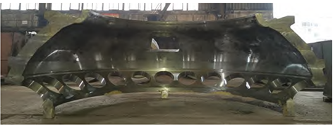
Figure 11 Roughing the top half of the shell
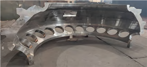
Figure 12 Lower half of the shell after roughing
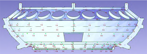
Figure 13 3D inspection data of the inner cavity of the shell after roughing
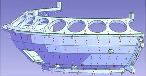
Figure 14 3D inspection data of the outer wall of the shell after roughing
According to the technical requirements, the casting as a whole was inspected MT, PT, UT, and from the non-destructive test results, the surface and internal quality of the casting met the design requirements.
5 Conclusion
The combustion chamber shell casting process scheme determined by MAGMA software-assisted design effectively guarantees casting shrinkage and dimensional quality, and avoids the risk of cracks. The casting process and physical quality of the combustion chamber shell casting are summarized, and the following conclusions are drawn:
(1) For castings with such thin-walled complex structures, zoning and segmented filling and shrinking methods are adopted, which can effectively ensure the internal quality of castings;
(2) Combined with the filling simulation results, the bottom-back and cut-in pouring system is used to effectively ensure the smooth filling of the molten steel during the pouring process and avoid the occurrence of porosity and slag inclusion defects;
(3) Through the MAGMA stress simulation results, the anti-deformation ribs and triangular ribs set by the castings of the combustion chamber shell effectively avoid the deformation and cracks of the castings; Dimensions simulated according to MAGMA The amount of shrinkage, correction and processing determined by the result is reasonable, which ensures that the size of the finished casting product meets the product delivery requirements;
(4) The combustion chamber shell casting adopts the method of upper and lower half casting, which can not only improve production efficiency but also prevent the deformation of thin-walled annular parts.