
Sand 3D printing is a fast production technology for making sand molds.This technology only requires the design of the casting through 3D modeling software.The pouring system is completed, the mold is divided, and the upper and lower molds and sand cores are designed.Afterwards, the designed upper and lower molds and sand cores are imported in STL formatSet up slicing in Magics, and thenimported into the 3D printer and began printing and producing sand molds.Compared with traditional sand casting, it does not require the production of master molds, reducing the production cost.cost;create sand molds and parts of any shape through 3D printing technologySand core;high accuracy of sand mold and sand core.Use sand mold 3D printing technologyCompared with traditional casting, the quality and production efficiency of casting are significantly improved.High.Based on the research on the casting process of sand-based 3D printing pump body, the casting process ofThe top-pouring, side-pouring and bottom-pouring gating systems are designed, usingAnycasting software conducted numerical simulation analysis to determine the optimal casting process.We have explored the application of 3D printing in sand casting, andThe casting is free of defects.
1. Design of pump body structure and classification method
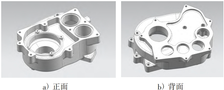
1.1 Pump body structureThe 3D model of the pump body is shown in Figure 1. This casting belongs to the shell categoryThe casting is asymmetric in structure.The overall dimensions of the pump body are 410 mm ×503 mm×170.5 mm, net weight 57 kg, belongs to small castings, materialIt is HT200.
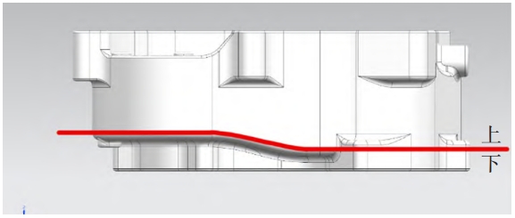
1.2 Determination of the parting surfaceThe choice of casting parting surface greatly affects the later printingWhether the completed sand mold can be successfully combined and the quality of the castings after pouring,Therefore, the following aspects are usually considered when selecting the parting surface:1) The fewer sand molds are used, the lower the error in casting will be, which also reduces the difficulty of assembling sand molds. Therefore, the design of sand moldsIt is necessary to reduce the number of parting surfaces of the sand mold as much as possible.2) Actual pouring experience shows that the inside or surface of the pouring partIn the case of a relatively complex structure and a relatively thin wall thickness, it is usuallyTry to ensure that these parts are placed on one of the sand blocks.3) The division of sand molds should take into account the later handling and assembly.The upper and lower molds of the sand mold are designed and transported according to the needsThe grip point should be of a combination type and have sufficient strength.Sand mold 3D printing technology is different from the traditional sand casting process, which requiresUse sand box, so the parting surface only needs to be optimized in sand mold 3D printing.First consider whether the final sand mold can be successfully formed, and then most castingsThe parting surface is usually selected at the maximum cross-section of the casting.Therefore, the parting surface of the casting is selected at the maximum cross-section of the casting.The area is shown in the figure. Through 3D software modeling, this scheme can beThe work-oriented type.
2. Scheme design and simulation analysis
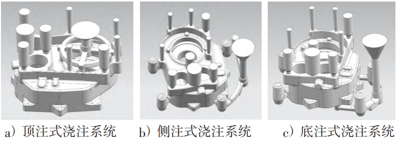
2.1 Design of pouring system schemeThree pouring schemes were designed for the pump body pouring system, including topThe injection type, side injection type and bottom injection type are shown in the figure.
2.2 Simulation analysis of filling process
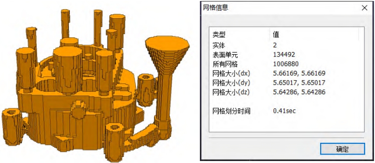
Use AnyCasting to conduct casting simulation analysis on the pump body,During the analysis process, it is possible to visually observe the casting after pouring is completedThe location and size of the defects that occurred after the test.Through numerical simulation, the defects were predicted.Improve the qualification rate of castings and reduce production costs.The inside of the pump body is an irregular cavity with varying wall thicknesses.According to the external dimensions of the casting, it is evenly divided into 1 millionregular cube grids, with an average size of5.6 mm×5.6 mm×5.6 mm as shown in the figure. Pouring process parametersAs shown in the table.
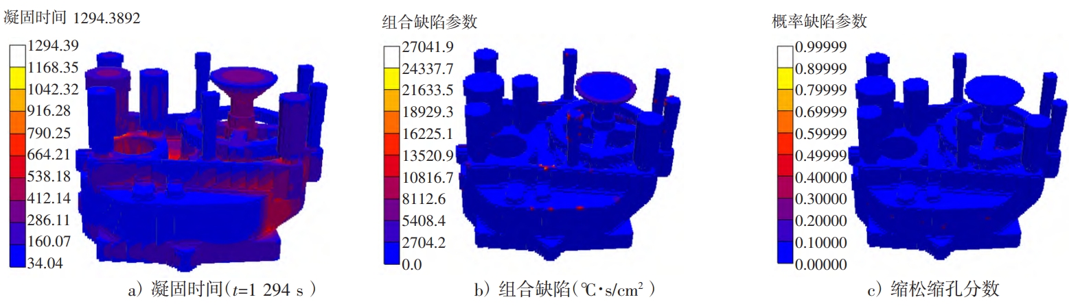
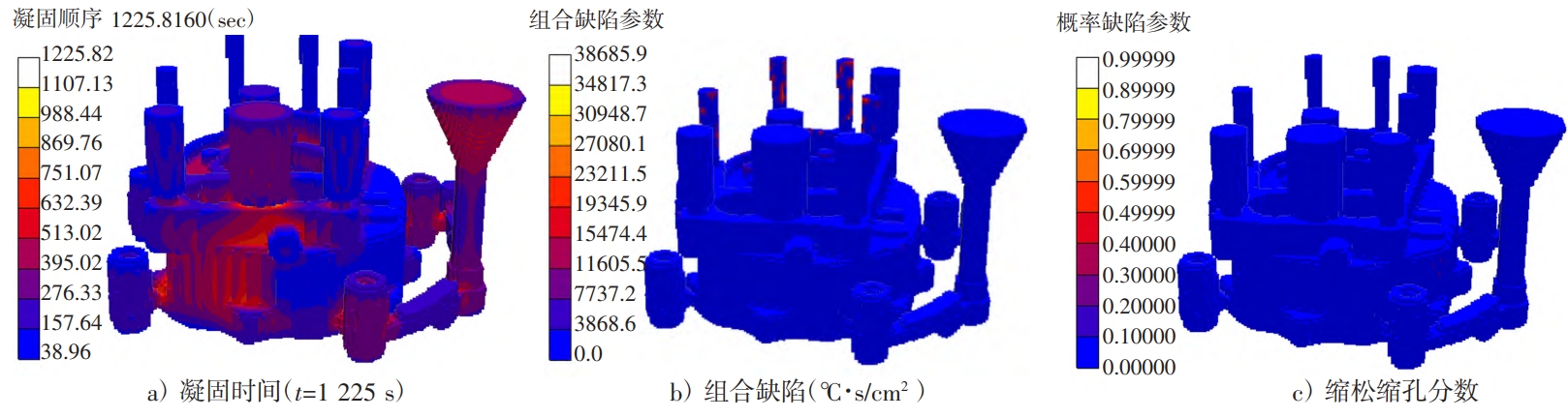
Simulation analysis of top-pouring scheme: overall design of top-pouring gating systemThe solidification sequence is from top to bottom and from outside to inside.The outer wall of the pump body casting is cooled first because it is thinnerHowever, the interior of the pump body casting is cooled last, as shown in Figure 5a).Through the analysis of combined defect parameters, the defects in the outer wall and the riser of the casting are analyzed.Defects may occur, as shown in Figure 5b.By using probabilistic defect parameters,Several pairs of workpieces were analyzed for porosity and shrinkage, and it was found that the porosity and shrinkage occurred in the casting.Defects on the outer wall and inner part are shown in Figure 5c).Simulation analysis of the side-pouring system: overallThe solidification sequence is also from top to bottom, from outside to inside.But theThe solid trend is uneven, excluding the riser and gate, pump body castingsThe outer wall of the pump body is cooled first because it is thinner, while the innerThe part is finally cooled, as shown in Figure 6a).Observe the combination of Figure 6bDefect prediction diagram and porosity and shrinkage fraction diagram in Figure 6c) reveal that the solidificationAfter that, shrinkage porosity defects appeared at the risers.The defects were basically notOn the casting, it does not affect the quality of the casting itself.Simulation analysis of the bottom-pouring scheme: the overall structure of the bottom-pouring gating systemThe solidification sequence is also from top to bottom and from outside to inside, butThe cooling is slower near the pouring system, as shown in Figure 7a).ObserveThe combined defect prediction diagram of Figure 7b) and the porosity and shrinkage porosity classification diagram of Figure 7c)In the vicinity of the joint between the riser of the casting system and the casting,There are birth defects, shrinkage porosity and shrinkage cavities in the middle hole wall and plane.When using a pouring system, the bottom runner has poor heat dissipation and the melt flow rateSlower, resulting in casting defects.According to the analysis results of the simulated pouring scheme, it can be concluded that the side pouringThe defects of the pouring system are concentrated in the riser, while the defects of the casting itself are few.There is almost no, so we choose the side pouring scheme.We choose nine risers,Place it on the surface of the workpiece to be processed in the later stage, with a height of the gate planeSimilarly, it is sufficient to allow the gas to be smoothly discharged and to be smoothly shrunk.
3 Practice Verification
Due to the complex structure and difficulty in modeling of the casting, the 3D printing method is used to print the sand core as shown in Figure 8.When printing the sand core, the designThe tapered size of the sand core can enhance the strength of the core fixation and facilitate placement.The sand mold is divided into 2 parts.Considering economic benefits, the printed sand mold isOptimization design of sand mold wall thickness can be carried out on the premise of ensuring strength,Reduce the amount of sand used.The printing of sand mold is done on Longyuan’s AFS-J1600 printerThe printing process is completed in the machine.After testing, it is finally determined that the printing process is divided intoLayer thickness is 0.4 mm, and the scan line width is 1.5 mm. Printing parametersAfter setting up, export the designed sand mold as an STL file andLayered processing, slicing with Magics, and setting the slicing as shown in Figure 9示。Then export the Magics output as a cli-format sliced model and import itGo to the AFS-J1600 printer to print.After printing, use a vacuum cleaner to clean the unbonded sand in the mold.The dry sand is washed, and the dust gun is used to clean it. The sand after cleaning isThe shape is shown in Figure 10.Before casting, it is necessary to spray zirconium on the casting surface of the sand mold.The powder is used to improve the surface quality of castings and reduce the amount of gas emitted to obtain higher quality castings after pouring, and to bake off excess moisture, leaving the sandKeep the mold dry, and pour the raw material HT200 at a pouring temperature of1 450 ℃, pouring time 18 s.After the casting is cooled, knock off the outer sand mold to obtain a non-obviousDefective castings, castings after removing the sprue and runner and pouring system, such asAs shown in Figure 13, the casting quality is qualified after inspection, and there is no obvious shrinkage porosity on the surface.And shrinkage cavity, the surface quality is good.

4 Conclusion
Using AnyCasting software, we can simulate the pump body side injection, top injection, andThe numerical simulation analysis of the bottom pouring scheme was conducted to determine the side pouringThe formula is the best pouring plan, which shortens the trial mold cycle;using 3D printingTechnical production of sand molds can greatly shorten the production time of sand molds;numerical modelingThe combination of proposed technology and sand mold 3D printing technology can greatly shorten the casting process.The development and trial production cycle of new products, improving production efficiency.