This type of beam is one of the main parts of a large machine tool. The quality of the casting is 28.9t, the material is gray cast iron, which belongs to large cast iron. The internal part of the casting is a “ten” type tie bar structure, with a wall thickness of 25 mm, many cavities, large wall thickness of the guide rail and the pressing plate surface on both sides. Meanwhile, the casting requires high quality of the guide rail surface and the pressing plate surface on both sides. Its shape is complex, the wall thickness is uneven, and the possibility of shrinkage defects is large.
Technical requirements for beam
(1) , the casting material is HT250, chemical composition (%): 3.0-3.2c, 1.7-2.0si, 0.7-0.9mn, P < 0.1, s < 0.08;
(2) . no shrinkage cavity, porosity and air hole are allowed on the processing surface of the casting. There are less than 10 holes per 300×300 on the non machined surface, otherwise it must be repaired.
(3) There shall be no sand sticking on the inner and outer surfaces of castings.
Casting process analysis
(1) , the wall thickness of the pressing plate surface at both ends of the casting is large, which is easy to have shrinkage cavity and porosity defects, so anti shrinkage measures must be taken.
(2) The mechanical properties of the casting are high and the casting is easy to stick sand, so the composition of the molten iron is required.
(3) There are many grades in the casting, and the possibility of porosity is high.
(4) . the casting has high requirements for non machined surface and limited requirements for loose defects, so it has requirements for sand mold strength.
Determination of original process plan
1)Chemical composition this casting not only has the limitation to the shrinkage cavity and the shrinkage porosity, but also has the higher request to the mechanical property of the casting. Therefore, the method to improve the silicon carbon ratio of the casting is to take the carbon equivalent not less than 3.5%, the silicon carbon ratio not less than 0.65, and finally determine the carbon and silicon content (%) as 3.0-3.1c, 1.9-2.0si. The carbon content in actual operation shall be the lower limit as far as possible, and the silicon content shall be the upper limit as far as possible.
In order to improve the mechanical properties of the casting, and in addition to the fact that the possibility of cracks in the reinforcement of the casting is relatively low, the requirement range of s content (%) is 0.6-0.8. In order to prevent sand sticking and consider the risk of shrinkage defects in castings, the P content (%) is approximately 0.3.
2) Molten iron temperature
Because of the possibility of porosity in crossbeam, it is necessary to increase pouring temperature to reduce the probability of porosity. At the same time, in order to reduce the shrinkage defects of the casting as much as possible, it is comprehensively determined that the pouring temperature of the casting is 1340 ℃
3) Sand mold conditions
Considering that the part also has limitation on shrinkage defects of non machined surface, the strength of sand mold is increased to more than 9kg / cm2, and the resin content is increased to 1.2%.
4) Setting of pouring system, riser and chill
According to the principle of casting technology, the selection of parting surface should be consistent with the pouring position. At the same time, the important position of machining surface and casting should be located at the lower part. According to the above two principles, the casting adopts horizontal parting, and key surfaces such as guide rail surface are set at the lower end. At the same time, in order to ensure the surface quality of the guide rail surface, cold iron shall be placed at the bottom of the guide rail surface.
In order to ensure that the molten iron can enter the mold cavity smoothly and prevent the casting from firing; at the same time, in order to ensure the surface quality of the guide rail surface and reduce the tendency of shrinkage defects at the thick and large positions at both ends, the two ends of this part adopt the stepped pouring system, while the side adopts the bottom pouring system. As for the riser system, in order to facilitate the smooth exhaust of the inner cavity, 26 25x40mm outlet risers are placed on the upper part of the casting; at the same time, based on the consideration of shrinkproof, 8 compression risers with diameter of 100mm are prevented at the places with large thickness at both ends.
Process plan simulation
Generally, there are three stages when using Huazhu CAE software for simulation:
(1) Through the use of three-dimensional software such as UG and Pro-E for h-dimensional modeling, and then use the pre-processing software to select the appropriate grid for division;
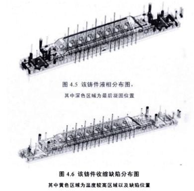
(2) , simulate the solidification temperature field and liquid phase area of the casting in the casting process (3), predict the possible shrinkage defects in each position of the casting through the above analysis, and show the WS dimension figure of the data obtained through the simulation calculation, thus providing a convenient way to predict the possible defects in each part of the casting.
It can be seen from the figure that the thickness of the head at both ends is large or the hot spot position and the fillet position of the middle upper end face, the molten iron solidifies finally, and the temperature is also higher than other parts, so the probability of shrinkage defects at the above positions is also higher than other positions. Although there is also a compression riser in this position for feeding, it can be seen from these two figures that the diameter of the compression riser is still small or the feeding capacity is not enough, and the hot metal feeding at the upper fillet position is poor.

Improvement measures
(1) In order to strengthen the sequential solidification, the feeding capacity of the cold iron reinforced riser is placed at the defect position at both ends:
(2) In order to ensure sufficient feeding of molten iron in the riser, increase the diameter of the riser at both ends to 140mm;
(3) Add the upper inner gate in the vertical direction of the same inner gate in the middle position, so as to directly supplement the fillet position, forming the same stage pouring system as the two ends.
Simulation of improvement plan
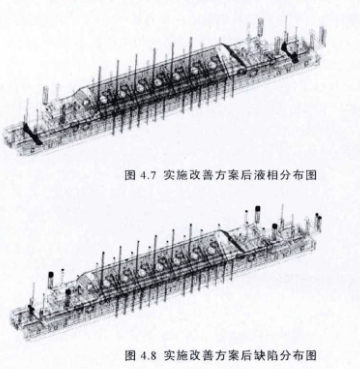
It can be seen from the figure that after the implementation of the improvement plan, the defects in the middle part of the casting have been solved, while the shrinkage defects are basically solved except that there are still shrinkage cavity and shrinkage porosity defects in two small parts of the thick positions at both ends. Therefore, the shrinkage of the casting can be basically solved by increasing the number of risers or pouring the risers at the time of pouring.

