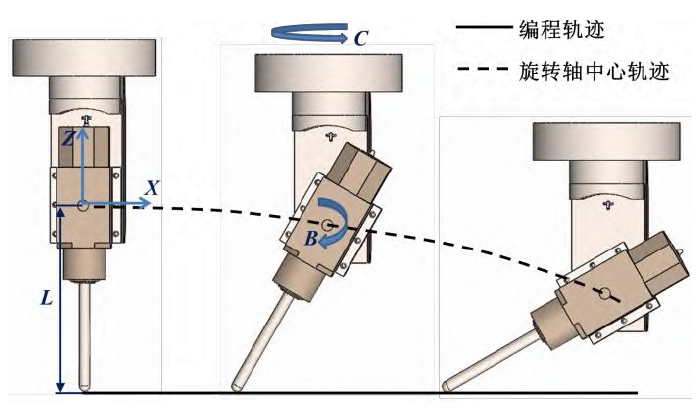
The five axis machine tool with double turntable structure has a smaller part size, while the sand mold is mainly composed of cavity and larger size, so it is suitable to use double swing head structure. The double pendulum head five axis equipment mainly has a-c and B-C two combination structures. In this paper, B-C double pendulum head structure is selected to study the control technology of sand mold five axis forming. The schematic diagram of 5-axis linkage RTCP with B-C double swing head structure is shown in Figure 1. When the programming path is a straight line, when b-axis or c-axis rotates, in order to maintain the tool tip point moving along the straight-line trajectory, it is necessary to adjust the x-axis, Y-axis and z-axis positions in real-time to compensate the position offset of the tool tip.

Establish the coordinate system of B-C double pendulum head sand mold five axis linkage forming, as shown in Figure 2. Among them, OM XM YM ZM is the sand mold workpiece coordinate system, the origin o m is the feature point of the workpiece profile, which is usually consistent with the origin set by CAM software; ot XT YT ZT is the tool coordinate system, its origin o t is located at the end cusp of the tool when the tool axis is parallel to the Z axis; or XR yr Zr is the rotation coordinate system, and the origin or is the intersection point of b axis and C axis rotation center line.
Assume the following conditions: all coordinate systems have the same direction as the machine coordinate system, which are rectangular coordinate systems and follow the right-hand Cartesian rule; the center line of the rotation axis is parallel to the coordinate axis, and there is no other deflection angle; the workpiece coordinate system om XM YM ZM and the tool coordinate system ot XT YT ZT only differ in the Z direction from the pendulum length L, x, y, Z In the initial position, the tool axis is parallel to the Z axis. According to the motion chain shown in Fig. 2, the position of OT in the workpiece coordinate system om XM YM ZM can be represented by the vector PM [PMX, PMX, PMX], and the position of or in the tool coordinate system ot XT YT ZT can be represented by the vector MT [0,0, l]. The cutter rotates around the b-axis and c-axis,the coordinate transformation can be expressed as follows:

The initial position of the tool tip in the rotary coordinate system or XR yr Zr can be expressed by the vector TL [0,0, – l]. When the tool rotation angles B and C, the position change of the tool tip after rotation in the workpiece coordinate system can be obtained by the rotation of the vector TL in the rotation coordinate system or XR yr Zr and the translation of the coordinate system or XR yr Zr relative to ot XT YT ZT. The position change caused by tool rotation in workpiece coordinate system can be expressed as follows:

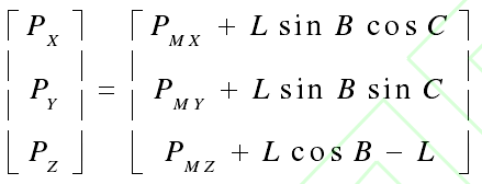
The core of RTCP is to keep the position of the tool tip in the workpiece coordinate system unchanged when the tool swing angle. Therefore, in the workpiece coordinate system, in order to keep the tool tip position unchanged, the linear axis coordinates P [Px, py, PZ] after tool rotation can be obtained by subtracting the tool position change from the original workpiece coordinate

The formula PM, Rb, Rb, MT are introduced into the formula

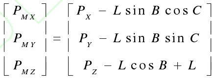
Series mechanical robot, parallel robot and five axis CNC machine tool RTCP are essentially coordinate transformation problems in Cartesian coordinate system. The forward and inverse kinematics solutions can be used to realize the position calculation. For B-C sand mold five axis linkage RTCP forming, the inverse kinematics solution takes the tool tip position at the end of the spindle as the input, and calculates the position of each motor reversely. The forward kinematics solution takes the position of each motor as the input, and calculates the tool tip position of the spindle end through b-axis and c-axis rotation transformation. According to the set period, the controller circularly calls forward and inverse solution programs, constantly refreshes the command position, and realizes the calling of programming coordinates and the inverse solution calculation of RTCP of each motor position. The forward kinematics formula can be obtained from the formula transformation

The formulas of forward and inverse solutions of B-C double swing head RTCP, namely formula (4) and equation (5), are packaged into PMAC controller. The controller will read the programming coordinates in the process of motion, automatically call the inverse kinematics RTCP algorithm, conduct real-time linear axis trajectory and interpolation calculation, and realize five axis simultaneous machining.
