
In my years of experience in foundry engineering, I have consistently focused on the production of high-integrity sand casting parts for demanding applications, such as those in electrical power systems. Among these, components like pressure-equalizing rings for high-voltage transformers stand out due to their stringent quality requirements. These sand casting parts must exhibit flawless surface finishes after machining and polishing, with no traces of porosity, shrinkage, or inclusions. The success in manufacturing such sand casting parts hinges on a holistic approach encompassing material selection, meticulous process design, and rigorous operational controls. This article delves into the intricacies of producing these critical sand casting parts, drawing from practical insights and technical principles to guide engineers and foundry professionals.
The pressure-equalizing ring, a quintessential example of precision sand casting parts, resembles a glass lampshade in geometry. Its key dimensions include a maximum outer diameter, height, and wall thickness, all of which dictate the casting strategy. For such sand casting parts, the primary objective is to achieve dimensional accuracy and superior metallurgical quality. The choice of material plays a pivotal role. In this case, a eutectic aluminum-silicon alloy, such as Al-Si12, is preferred due to its excellent castability, fluidity, and machinability. This alloy minimizes hot tearing and enhances feedability, crucial for thin-walled sand casting parts. The eutectic composition offers a narrow freezing range, reducing the risk of shrinkage defects, which is paramount for sand casting parts destined for electrical insulation duties.
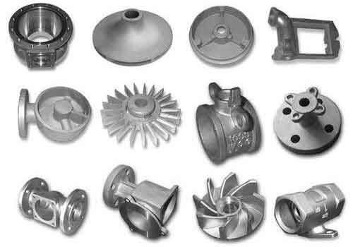
A well-considered casting process design is the backbone of producing defect-free sand casting parts. For the pressure-equalizing ring, the parting line is strategically placed at the largest cross-section, with the closed end oriented downward in the mold. This orientation leverages gravity to promote filling and feeding. A suspended core is employed to facilitate gas escape—a critical aspect for sand casting parts where entrapped air can lead to blowholes. The upper mold section incorporates machining allowances; for planar surfaces, a minimum allowance is maintained, while spherical regions require process padding, known as a “padding” or “feeder head,” to accumulate molten metal and trap oxides and slag. The thickest section of this padding should be designed to ensure adequate metal supply. To combat shrinkage and non-metallic inclusions, three evenly spaced risers, each with a specific diameter, are positioned atop the casting. These risers serve as reservoirs and escape routes for impurities. The gating system comprises a sprue, with a defined diameter, and ingates of specified dimensions, arranged to ensure smooth, turbulence-free filling. Shrinkage allowances are factored into the pattern dimensions to achieve final part accuracy. For sand casting parts like this, a shrinkage rate of approximately 1% is typical, though it varies with alloy and geometry. The machining allowances on sides and bottom are uniformly applied, as dimensional tolerances on outer diameters are relatively lenient compared to surface quality demands.
Beyond design, execution details are vital. Additional features, such as chucking lugs and center points for lathe machining, are integrated into the pattern to aid post-casting operations. The core is fabricated using resin-bonded or sodium silicate sands, ensuring adequate strength and collapsibility. A core vent or suspension rod is embedded to enhance gas permeability. For mold alignment, precision is paramount; dowel pins are used to register the cope and drag halves, preventing core misalignment. During melting, the aluminum alloy undergoes rigorous degassing and modification treatments to eliminate hydrogen and refine the silicon phase. The pouring temperature is tightly controlled within a optimal range, typically between 680°C and 710°C, to balance fluidity and shrinkage. As the mold fills, risers are topped up to promote directional solidification. These steps collectively ensure that sand casting parts meet the high standards required for electrical applications.
To encapsulate the key parameters for such sand casting parts, I present the following tables. These summarize the geometric, material, and process variables that govern the production of high-quality sand casting parts.
| Parameter | Value | Notes |
|---|---|---|
| Maximum Outer Diameter | Approx. 600 mm | Critical for electrical clearance |
| Height | Approx. 300 mm | Influences mold filling dynamics |
| Wall Thickness | Uniform, e.g., 8-10 mm | Minimizes thermal gradients |
| Material | Eutectic Al-Si Alloy (e.g., AlSi12) | Chosen for castability and finish |
| Surface Quality Requirement | Free of pores, inclusions post-polish | Non-negotiable for insulation |
| Process Element | Specification | Rationale |
|---|---|---|
| Parting Line Location | At largest diameter | Simplifies molding and core placement |
| Core Type | Suspended, vented | Enhances gas evacuation |
| Riser Diameter | e.g., 40 mm (3 nos.) | Provides feed metal and slag trap |
| Sprue Diameter | e.g., 30 mm | Controls flow rate |
| Ingate Dimensions | e.g., 20 mm × 5 mm | Ensures laminar flow into cavity |
| Shrinkage Allowance | 1.0% | Compensates for solidification contraction |
| Machining Allowance (Planar) | ≥ 3 mm | Allows for surface cleanup |
| Process Padding Thickness | Up to 15 mm at maximum | Acts as a feeder and impurity collector |
| Pouring Temperature | 680–710°C | Optimizes fluidity while minimizing shrinkage |
| Degassing Treatment | Mandatory (e.g., rotary degassing) | Reduces hydrogen-induced porosity |
The manufacturing of sand casting parts like these often involves calculations to predict behavior. For instance, the final dimension of a sand casting part can be derived from the pattern size using the shrinkage allowance formula:
$$ L_f = L_p \times (1 + s) $$
where \( L_f \) is the final casting dimension, \( L_p \) is the pattern dimension, and \( s \) is the linear shrinkage rate (expressed as a decimal). For a typical aluminum sand casting part, \( s \approx 0.01 \). Similarly, the gating system design can be optimized using fluid dynamics principles. The flow rate \( Q \) through a sprue can be approximated by:
$$ Q = A \cdot v $$
where \( A \) is the cross-sectional area and \( v \) is the velocity, which depends on the head height \( h \) and gravitational acceleration \( g \):
$$ v = \sqrt{2gh} $$
These formulas aid in designing efficient gating for sand casting parts, minimizing turbulence that can entrap oxides. Moreover, the solidification time \( t \) for a sand casting part, critical for predicting shrinkage, can be estimated using Chvorinov’s rule:
$$ t = B \left( \frac{V}{A} \right)^n $$
where \( V \) is volume, \( A \) is surface area, \( B \) is a mold constant, and \( n \) is an exponent (typically around 2). For thin-walled sand casting parts, a high \( A/V \) ratio leads to rapid solidification, necessitating careful riser placement.
Quality assurance for sand casting parts extends beyond process control. Non-destructive testing methods, such as radiography or dye penetrant inspection, are employed to detect subsurface defects. For electrical components, dielectric strength tests may also be conducted. The goal is to ensure that every sand casting part performs reliably in service, underscoring the importance of a robust manufacturing protocol.
Expanding the discussion, the principles applied to aluminum sand casting parts can be adapted to other materials, such as ductile iron, for components like gears and crankshafts. For example, austempered ductile iron (ADI) parts, produced via sand casting, require precise heat treatment to achieve a matrix of austenite and bainite, offering high strength and toughness. The isothermal transformation process involves holding at an intermediate temperature to form bainite, but the “window” for this transformation must be carefully controlled to avoid deleterious phases like martensite or carbides. Alloying elements like molybdenum, nickel, and copper are added to widen this window, enhancing process robustness. Post-austempering, a low-temperature tempering may be applied to convert any martissite to tempered martissite, further improving toughness. The properties of such sand casting parts are influenced by composition and heat treatment parameters, as summarized below.
| Parameter | Effect on Microstructure | Impact on Mechanical Properties |
|---|---|---|
| Isothermal Temperature | Higher temperature increases austenite retention | Enhances ductility and impact resistance |
| Isothermal Time | Short time may lead to martensite; long time promotes carbide precipitation | Optimizes toughness within a “window” |
| Tempering Temperature (e.g., 200–300°C) | Converts martensite to tempered martensite | Reduces brittleness while maintaining strength |
| Alloying (Mo, Ni, Cu) | Delays carbide formation, stabilizes austenite | Broadens processing window, improves consistency |
The relationship between tempering temperature and properties for these sand casting parts can be expressed empirically. For instance, the hardness \( H \) after tempering might follow:
$$ H = H_0 – k(T – T_0) $$
where \( H_0 \) is initial hardness, \( k \) is a material constant, \( T \) is tempering temperature, and \( T_0 \) is a reference temperature. Such models help in tailoring heat treatments for specific sand casting parts.
In recent years, advancements in sand casting parts technology have addressed challenges like producing thick-section ADI components or achieving as-cast austempered structures. Research into welding, fatigue, and fracture behavior of these sand casting parts continues to deepen. Standards have been established in various countries to codify best practices, facilitating wider adoption. For instance, in automotive applications, sand casting parts like ADI gears and crankshafts are now commercially produced, demonstrating the viability of sand casting for high-performance parts.
To further illustrate the interdependencies in producing sand casting parts, I present a consolidated framework of key factors. This matrix highlights how material, design, and process variables interact to influence the quality of sand casting parts.
| Factor Category | Specific Variables | Influence on Casting Quality | Optimal Range for Electrical Components |
|---|---|---|---|
| Material | Alloy type, Si content, impurity levels | Fluidity, shrinkage tendency, machinability | Eutectic Al-Si alloys; low Fe, Cu |
| Mold Design | Parting line, core design, gating geometry | Filling behavior, gas escape, defect formation | Bottom gating, suspended cores, multiple risers |
| Process Parameters | Pouring temperature, degassing, modification | Porosity, inclusion content, surface finish | 680–710°C, thorough degassing, Sr or Na modification |
| Heat Treatment (if applicable) | Isothermal temperature/time, tempering | Microstructure, mechanical properties | Tailored to achieve austenite-bainite matrix |
| Quality Control | NDT, dimensional checks, dielectric tests | Reliability in service | 100% inspection for critical surfaces |
The economic and technical benefits of optimizing sand casting parts are substantial. By reducing scrap rates and enhancing performance, foundries can deliver value in sectors like power transmission and automotive. For example, the pressure-equalizing ring, as a sand casting part, exemplifies how tailored processes yield components that meet exacting electrical standards. Similarly, ADI sand casting parts showcase the versatility of sand casting in producing high-strength, wear-resistant components.
In conclusion, the production of high-integrity sand casting parts demands a synergistic approach. From material selection to detailed process design and stringent operational controls, every step must be meticulously planned and executed. The use of alloys like eutectic Al-Si for electrical parts or ADI for mechanical parts underscores the adaptability of sand casting. Formulas and tables, as presented, serve as practical tools for engineers to predict and control outcomes. As technology evolves, innovations in molding materials, simulation software, and quality assurance will further enhance the capabilities of sand casting parts. For professionals in the field, mastering these elements is key to manufacturing sand casting parts that excel in performance and reliability, driving progress in industries reliant on precision metal components.
Reflecting on my journey, I emphasize that continuous learning and adaptation are essential. Each project involving sand casting parts brings new challenges, but the fundamental principles remain: understand the material, design for manufacturability, control the process, and verify the quality. By adhering to these tenets, we can push the boundaries of what sand casting parts can achieve, enabling advancements in everything from energy infrastructure to transportation. The future of sand casting parts is bright, with ongoing research paving the way for even more sophisticated applications.