If the sand mold casting process is unreasonable, the local hot spots of the casting shell will increase. In order to ensure the compactness of the internal structure of the casting and effectively prevent sand casting defects such as looseness and shrinkage cavity in the thick parts of the shell, it is necessary to ensure the solidification sequence from the sand casting body to each riser. The produced shell also needs to conduct a hydrostatic test on the inner cavity to prevent leakage of the sand casting during use.
1.Modeling method
As the shell of this model has small production volume and high requirements for appearance quality, it is determined to adopt manual molding and core making methods. According to its structural characteristics, the sand box molding and casting method combining the solid sample mold and core assembly is adopted as a whole. The resin sand mold has good yielding, which can increase the shrinkage of sand castings. Therefore, the resin sand is used for the external mold and clay core, and the clay core in key parts Chrome iron ore sand material shall be used at the fillet of sand mold casting and the parts prone to sand sticking.
2.Selection of parting surface
According to the characteristics that the sand mold casting is a box frame structure as a whole, it is decided to adopt the vertical casting method. Although the mud core of the motor barrel and the mud core of the reducer are easy to be fixed and not easy to float, the rest of the mud cores are difficult to be fixed. Therefore, this modeling scheme is difficult to ensure the accuracy of the sand mold casting, and the increase of the parting surface will lead to the increase of the sand mold height, which will bring difficulties to the modeling and pouring operations. Considering the feeding of thick parts of sand castings, horizontal pouring method can be adopted. The parting surface is divided symmetrically in the horizontal direction of the center of the shaft hole of the motor barrel, which is conducive to the setting of risers, improving the feeding efficiency of risers, realizing sequential solidification, eliminating shrinkage cavities and porosity, and ensuring the dense sand castings.
3.Determination of process parameters
(1) Draft angle
In order to facilitate mold removal (or take out the clay core from the core box), the vertical wall of the mold should be made into a slope extending to the parting surface. The method of increasing the wall thickness of sand castings is generally adopted for the surface to be machined by sand castings. Design the draft angle of the rocker arm housing according to the structure of the sand casting and the design requirements of the drawings α= 1.50°。
(2) Core size design
The core head is a technological measure to support and fix the mud core. In order to make the mud core work reliably, it is necessary to make the core head have appropriate size.
① Length of core head the core shall be subject to the impact and buoyancy of gravity and liquid metal. In order to ensure the stability of the core position and avoid the core seat being crushed, the core head shall have sufficient length. However, the size of the core head is too large to make the size of the sand mold larger. The length of the core head is generally determined according to the length and section size of the core. According to the structural characteristics of sand mold castings and the production process equipment, the length of the mud core head of the rocker shell is set: the length of the mud core head at the planetary head position is 350 mm at the coal wall side, 300 mm at the gob side, 250 mm at the first and third axes, 550 mm at the four to seven axes at the coal wall side, 250 mm at the motor barrel orifice, and 400 mm at the large plane at the gob side.
② Core head inclination in order to avoid damaging the sand mold when the lower core and the box are closed, the core head shall have an inclination. The inclination of the upper core head of the vertical core head shall be slightly greater than that of the lower core head, so as to facilitate the box closing. The core head draft angle is designed to be 3 °.
③ Core head clearance there should be assembly clearance between the core head and the core base. The deformation of the mud core during the manufacturing, transportation, drying and other processes will affect the core head clearance. According to the structural characteristics of sand mold casting of rocker arm housing and combined with practical experience, the core head clearance is designed to be 4 mm.
(3) Reservation of machining allowance
The machining allowance shall be reasonably selected. If the machining allowance is too large, the material cost and machining cost will be increased. Sometimes, the hot spot will increase due to the too thick section, resulting in coarse grains of sand castings, resulting in shrinkage or porosity; If the machining allowance is too small, it will lead to insufficient cutting allowance, requiring repair welding or even scrapping. After trial production of test bar, it is finally determined that the machining allowance of sand casting is 15 mm for upper and lower planes, 15 mm for both sides and 18 mm for shaft hole.
4.Gating system design
Due to the complex shell structure, in order to effectively avoid sand inclusion, scab, wrinkle, cold shut, insufficient pouring and other defects, it is necessary to have sufficient pouring temperature and filling speed to obtain sand castings with clear contour. In order to ensure the stable filling of the pouring system and avoid turbulence, gas inhalation and excessive speed of molten metal entering the mold cavity, it is decided to adopt the bottom pouring system to make the molten metal filling stable, It is beneficial to solidification or feeding of sand castings. In order to prevent sand flushing, the gating system is made of ceramic tubes.
5.Riser design
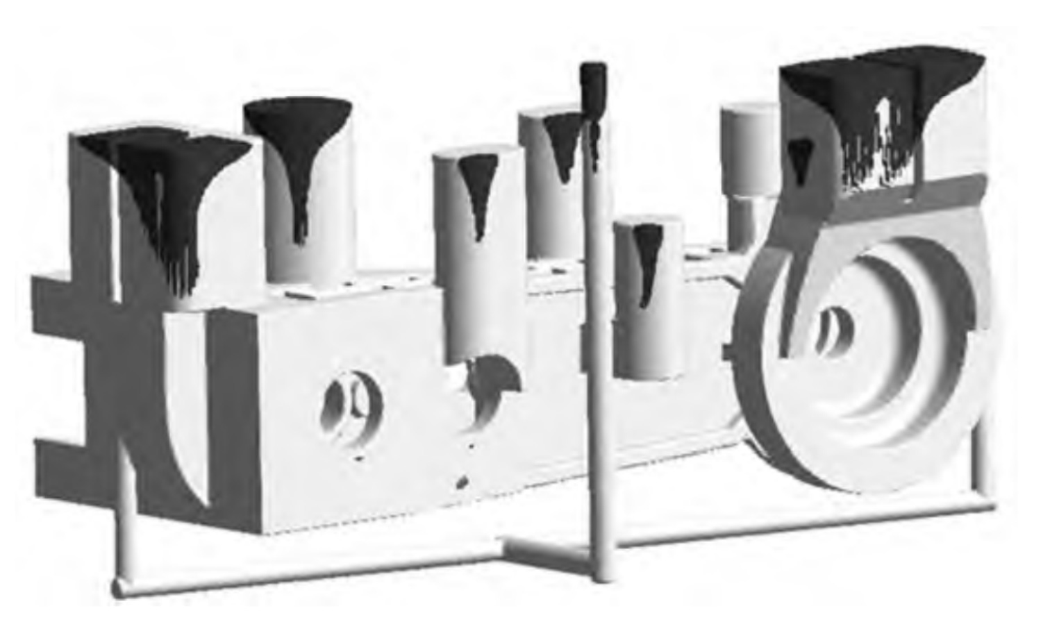
The hot spot of sand mold casting is analyzed by computer simulation software. According to the simulation results, the feeding area is preliminarily divided, and each feeding area corresponds to a riser. Determine the module of the riser by the size of the hot spot at the feeding position of the riser. Finally, analyze it through the simulation software, and further refine the simulation to minimize the size of the riser. The layout of the riser position is shown in Figure 1. The dark part is the riser, and a total of 9 risers are set. Wooden square open risers with a size of 850 mm are selected at the planetary head and the cylinder × 500 mm × 1000 mm, 2 arranged on the upper plane of the rocker arm φ 320 mm × 415 mm concealed riser, 1 No. 220 mm × 330 mm × 285 mm concealed riser, 1 x 260 mm × 390 mm × 340 mm concealed riser, 1 No φ 260 mm × 310 mm concealed riser, 1 No. 280 mm × 420 mm × 365 mm concealed riser. In order to extend the feeding distance of riser in the inner cavity of motor barrel, open riser is added φ 400 mm。
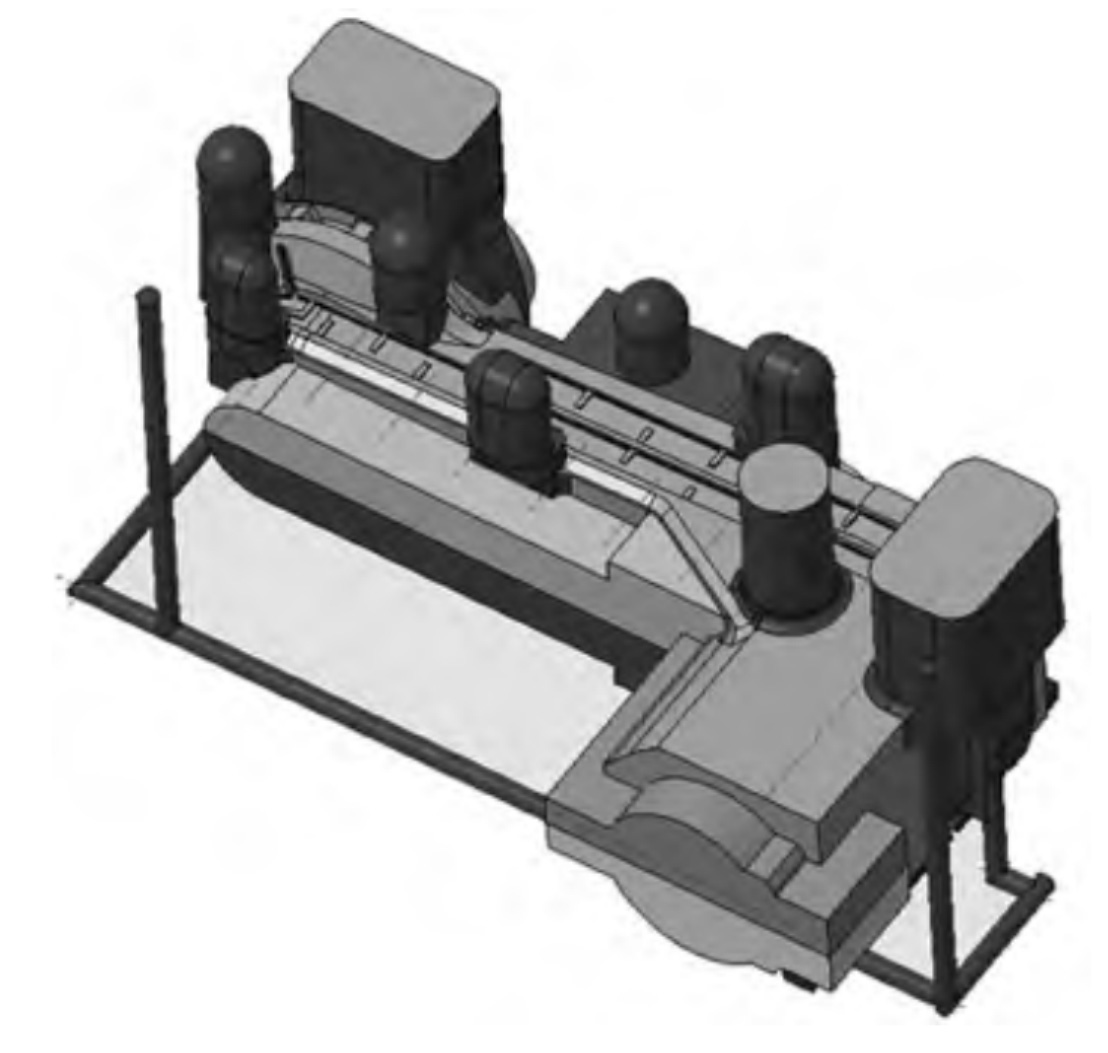
After the riser is arranged according to the above positions, the simulation diagram of sand mold casting scheme is shown in Figure 2. It can be seen from Figure 2 that the shrinkage and porosity defects in the area near the riser can be solved, but there are still porosity defects in the shaft hole of the shell and the part at the bottom away from the riser.
6.Design of external cooling iron
There will be a blind area if feeding only depends on the riser, which requires the use of external cooling iron to improve the feeding distance of the riser.
According to the structure of sand castings, in order to expand the feeding distance of risers, reduce the number of risers, make the feeding channel of risers more unblocked and reduce the feeding blind area, it is necessary to reasonably set external chill, so as to prevent shrinkage cavities and loose defects at the parts where it is difficult to feed risers, eliminate cracks and defects at the parts where the wall thickness changes sharply, and improve the local metallographic structure and mechanical properties of sand castings.
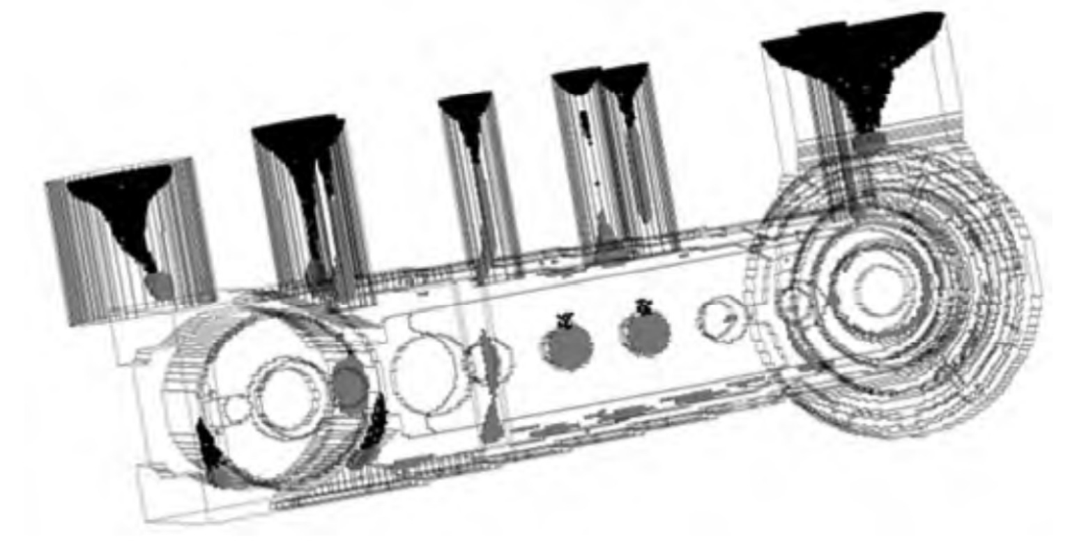
The sand mold casting process scheme after adding chill is shown in Figure 3, and the dark part is chill. Set 50 pieces with a size of 220 mm on the plane of the lower box of the housing motor barrel × 100 mm × 100 mm external chill to prevent looseness in the motor barrel; Four pieces with a size of 200 mm are set at the end face of the first shaft of the housing × 100 mm × 100 mm external chill to improve the density inside the shaft hole and prevent loose defects; Set 20 pieces of 200 mm near the water channel at the bottom of the rocker arm housing × 100 mm × 100 mm external chill to prevent looseness; Three 400 mm pieces are set at the bottom of the lower box of the rocker planetary head × 200 mm × 100 mm external chill to prevent sand casting defects on the planet head.
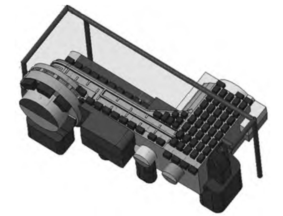
The simulation diagram of sand mold casting process scheme after adding chill is shown in Figure 4. It can be seen from Figure 4 that the shrinkage cavity and porosity defects inside the shell have all disappeared, and the sand casting process scheme after adding external chill meets the drawing design requirements.