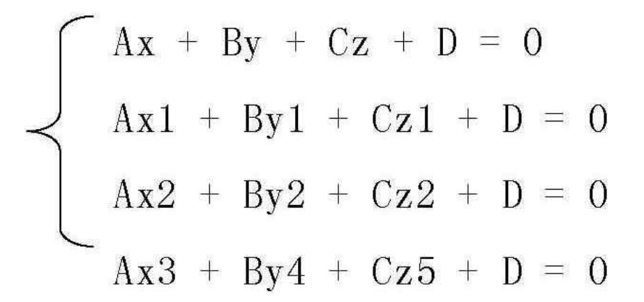
Sometimes it is necessary to know the internal information of sand castings, so it is also necessary to display the solid section of the grid. Therefore, in order to observe the relevant information of the specific section grid, it is necessary to realize the section observation and display of any section in the numerical simulation software. Here, there are two main cutting methods: one is to use the additional clipping surface function provided, and the other is to display the mesh on the specified plane. The application of additional cutting surface function is quite convenient and can be used to test the correctness of mesh generation results. However, due to hard cutting, the cut surface effect is abrupt and the image is not beautiful. When the mesh of the specified plane is displayed, the display effect is better, but the speed is slightly slower. In solid geometry, the plane is determined by the following equation:
The normal vector of a given plane and a point on the plane or three points on a known plane that are not on the same straight line are obtained according to the plane equation:
The values of a, B, C and D can be solved according to the above formula. By selectively displaying the mold grid of sand casting under the above formula, the sectioning observation of any section can be realized. For the sake of graphic display and convenient operation, the minimum and maximum values in three directions of sand casting are displayed. For segmentation, directly input the grid number of the three directions to be segmented in the segmentation input area, or slide the corresponding slider on the right to refresh the display immediately.
The following is the internal segmentation observation by taking the sand mold casting process of grinding ball as an example through the above method. The segmentation function is realized to observe the details inside the sand casting entity. The position in the X direction of the sand mold is the position in the X direction of the casting.
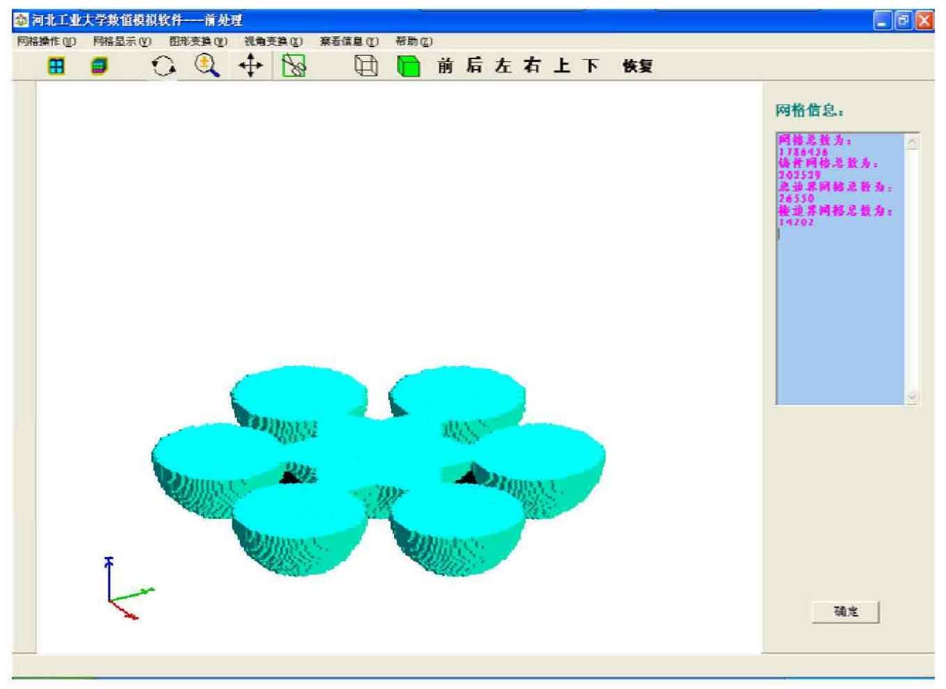
Fig. 2 is a sectional view of a certain position of sand mold casting in the Z direction.
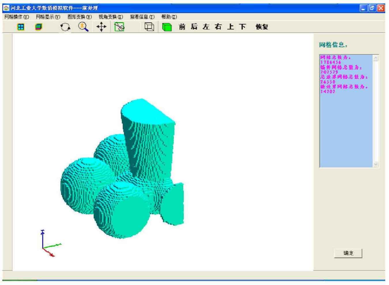
Fig. 3 is a sectional view of a certain position of sand casting in X and Y directions.


