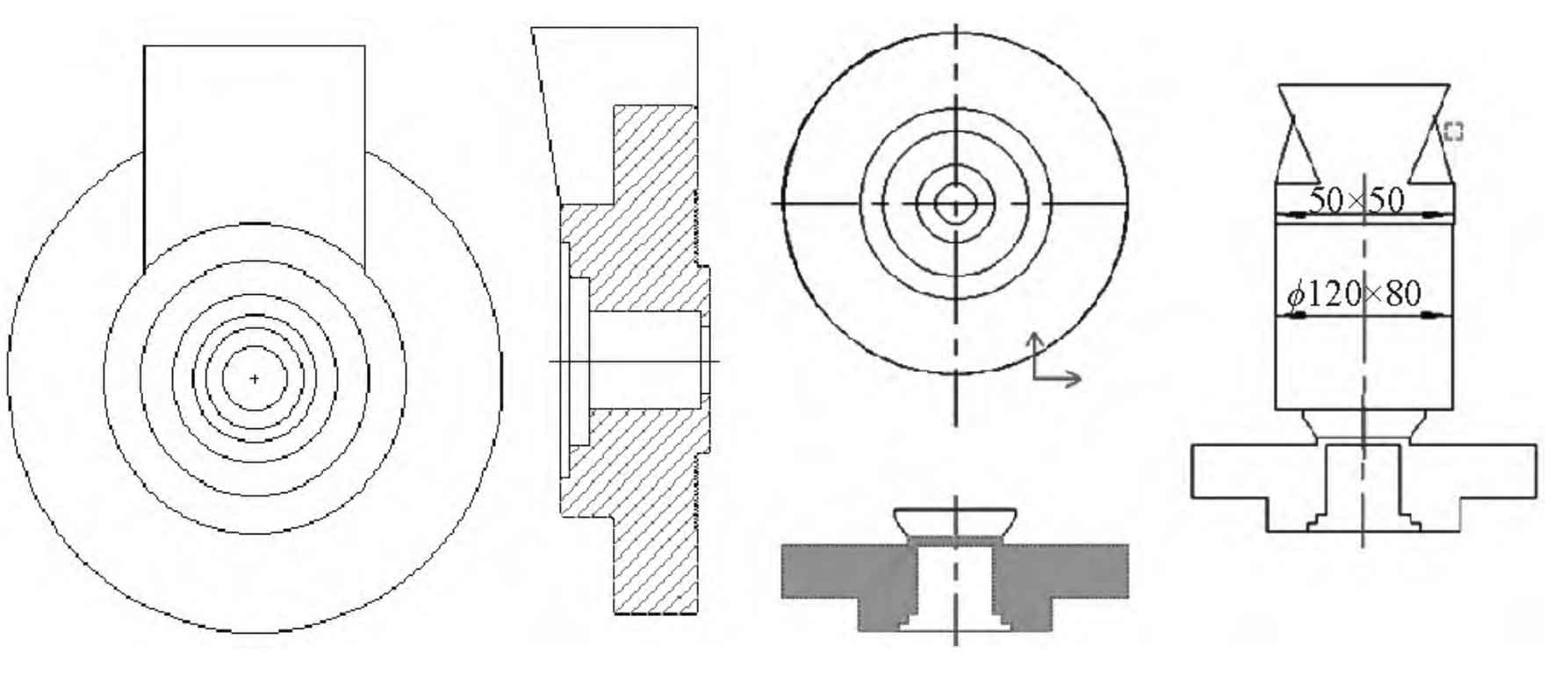
Figure 1 is the schematic diagram of the inner runner of a thick and large casting. After pouring, shrinkage porosity appears at the root of the inner runner of the casting, because the inner runner increases the internal hot spot of the casting. Plug the middle hole of the casting with 1/4 length, and change the position of the inner gate to the middle position of the casting, so that the casting can be fully shrunk, as shown in Figure 2.
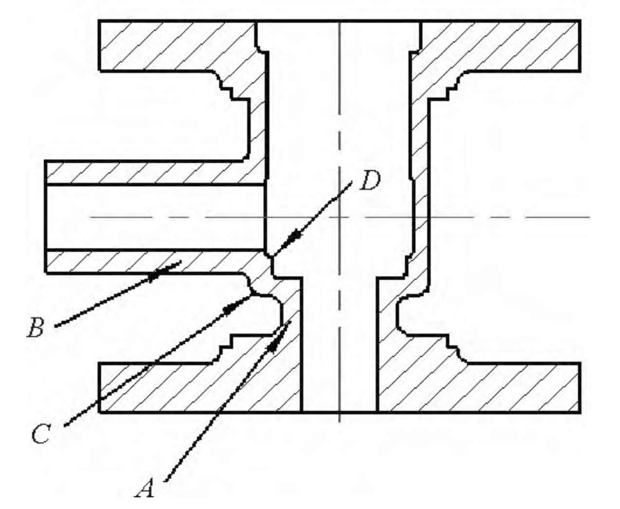
Figure 3 is a sectional view of a flange casting. The casting C is a hot spot, and the original process plan is shown in Figure 4. After pouring, the shrinkage defect appears at the C part of the casting, and the shrinkage defect appears at the D part after processing, which may be caused by local overheating of the shrinkage part. The improved process scheme is shown in Figure 5. The cooling condition is improved by local quenching before pouring, and the shrinkage defect of casting is solved.
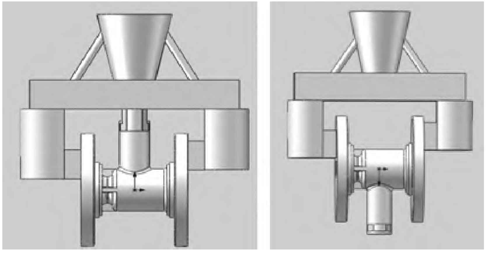
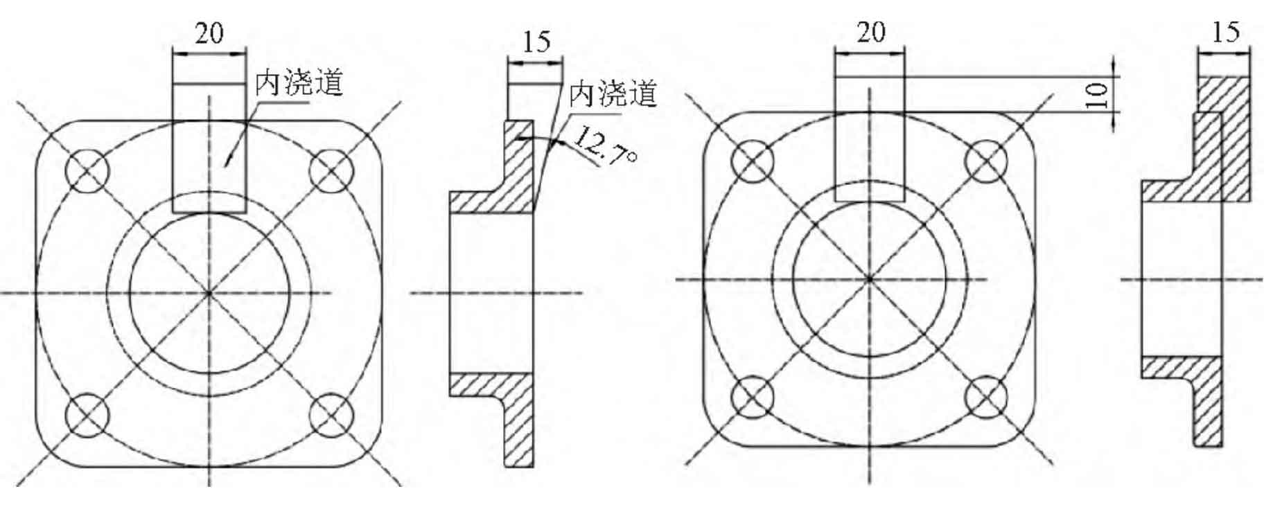
Figure 6 is the schematic diagram of a wedge-shaped ingate of a thin-walled flange casting. Slight shrinkage defects occurred after the processing of the gate position of the casting end face. The reason is that the wedge-shaped ingate cooled too fast at the casting end face and did not play the role of feeding the casting. See Figure 7 for the improved ingate scheme. By changing the ingate into a rectangular one, the cooling speed of the outer part of the ingate is reduced, so that the ingate can fully feed the casting, thus eliminating the shrinkage problem.