
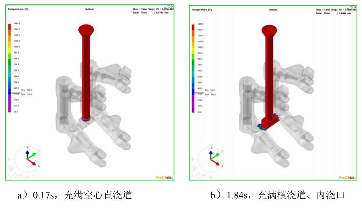
Figure 1 a) ~ g) shows the change process of mold filling temperature field of bottom injection trial production scheme. Figure a) it can be seen that the molten metal is filled with hollow runner just for 0.17 seconds, and the high temperature metal starts to connect with the foam pattern. The color of the front end of the mold is fluctuated, indicating that the metal liquid starts to form the foam pattern. The appearance of the mold results in the decrease of the temperature of the molten metal at the front of the mold filling. Figure b) for the molten metal, the transverse runner and ingate begin to invade the long fork part of the nodular cast iron. The time is 1.84s, and the pouring time is several times that of the hollow runner. This indicates that the existence of the foam pattern greatly reduces the filling ability of the molten metal, which greatly reduces the filling speed of the gold solution and directly slows down its further filling.
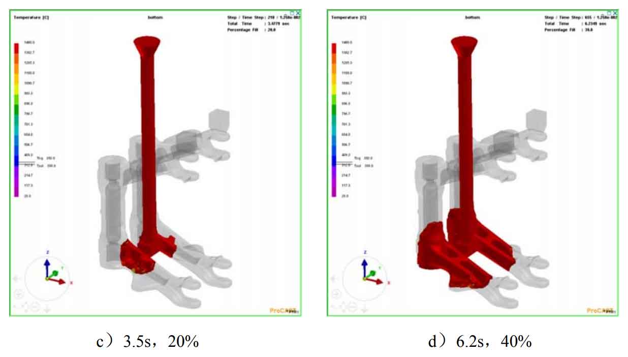
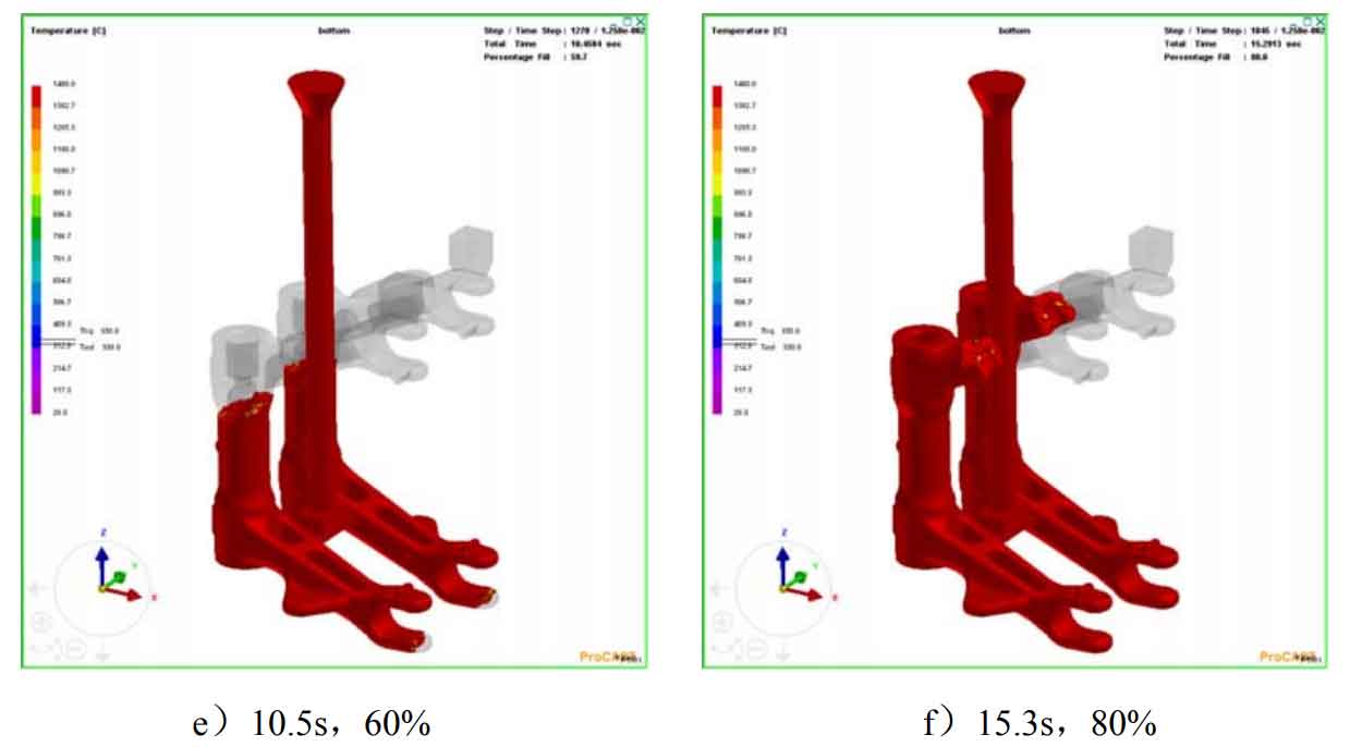
It can be seen from figure C) ~ g) that the time taken for each 20% forward filling is 3.5s, 2.7s, 3.3s, 4.8s and 8.8s in turn. The whole pouring process shows a trend of slow first, fast then slow, without flow interruption. The reason for slow first is that the molten iron temperature is high in the early filling stage, the degradation pattern is rapid, and the gas generation is large, but the ability of paint and dry sand to escape products is limited, This leads to the increase of the accumulated back pressure of the gas at the front end of the filling, which hinders the further filling of the molten iron. Next, the temperature of the molten iron decreases, and the filling speed will increase. The last stage of the filling takes the longest time, and the distance from the molten iron to the far end is far. The more heat lost on the way, the worse the filling capacity.
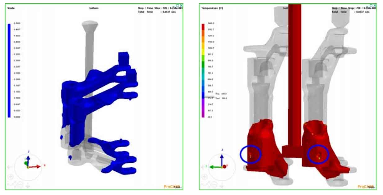
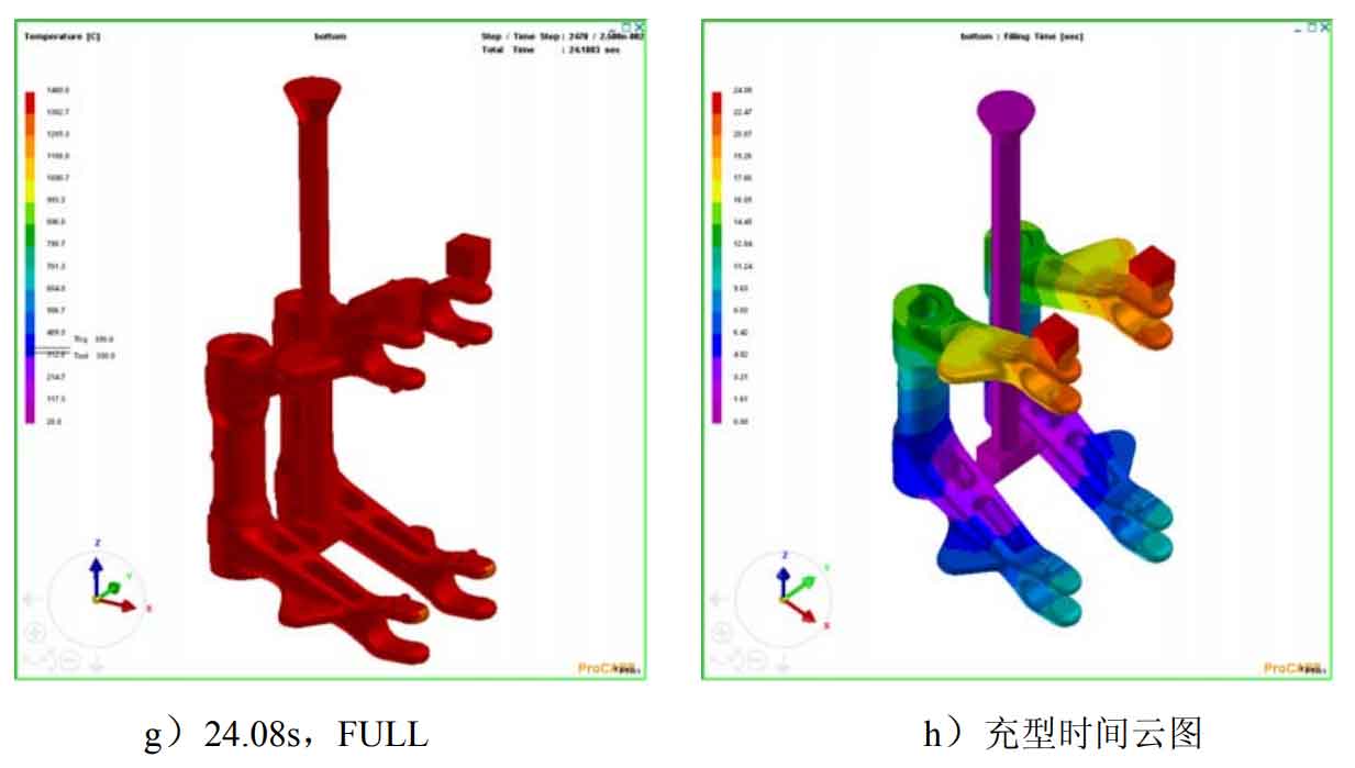
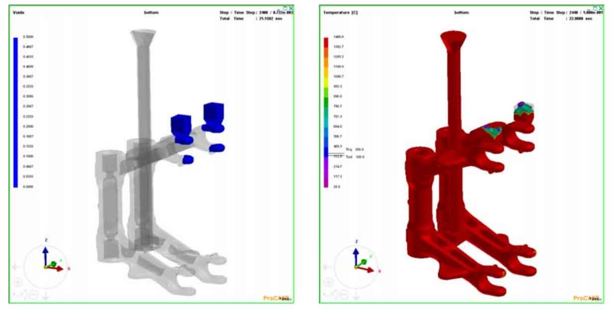
Fig. h) is a schematic diagram of the filling time distribution of the bottom injection type. The maximum filling time is 24.08s, and the actual filling time in the trial production process is about 25s. The results are very close. On the one hand, the small difference in filling time may come from the fact that the existence of a small amount of binder in the actual pouring process slows down the filling of metal liquid, On the other hand, the hollow foam straight runner has a thin layer of foam pyrolysis which will take away the heat of the molten metal in the simulation. The filling sequence can also be seen from the filling time cloud diagram. The liquid metal moves from the inner gate to the far end layer by layer, and the final filling position is the farthest from the inner gate, just at the small slag collecting riser at the top. At last, the metal fluid at the filling position experienced the farthest stroke, and the temperature dropped much more than other parts. Therefore, the ability of the metal liquid to degrade the foam was relatively poor, and the foam gasification rate was relatively low. At the same time, the slag discharge performance of the coating at the end of filling position also decreased with the filling process. The arrangement of slag collecting riser at this place can help discharge slag and exhaust gas, and avoid lost foam casting defects such as slag inclusion and pores.
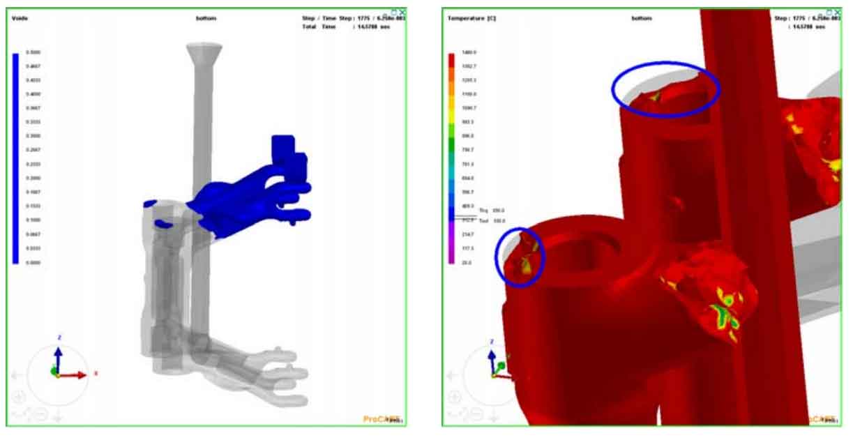
Looking at the Void results, we can see the burning process. We find that the material in the thick walled area below the cylinder is surrounded by the metal liquid. The foam pattern is floating in the process of degradation. The shape is likely to be wrapped in molten metal in solid or liquid form. If the residual foam and gas after combustion can not be discharged in time, Finally, the slag and slag hole were formed on the top of the long ductile iron casting. The principle of simultaneous interpreting sand casting was wrapped in gas, as shown in Figure 2. Figures 3 and 4 show the dead corner areas of late mold filling, such as the top of the cylinder and the front end of the fork. It is possible that the slag inclusion, inclusion and pore lost foam casting defects may be caused by the decline of liquid metal mold filling capacity and the poor slag discharge and exhaust environment in the dead corner area. From the actual slag discharge situation, the slag collection riser at the front end of the upper arm plays the role of slag collection and exhaust. However, due to the small volume of a single ductile iron long fork, the amount of slag left here is small.
From the whole filling process, the bottom filling type is more stable. During the filling process, though the metal liquid filling front has a slight temperature fluctuation, the overall temperature has remained relatively high, and the fluidity has been maintained well. The foam outside the dead zone can be fully degraded without any defects such as slag inclusion and wrinkled skin. The filling process is continuous without flow interruption, and there will be no box collapse.