Although adopting the horizontal casting process scheme can greatly reduce the production cost and improve the production efficiency, it is necessary to solve the problems of large plane inclusion of the impeller and local loose shrinkage of the impeller casting. The specific measures are as follows:
(1) Solve the problem of scattered shrinkage and looseness at local position of impeller casting

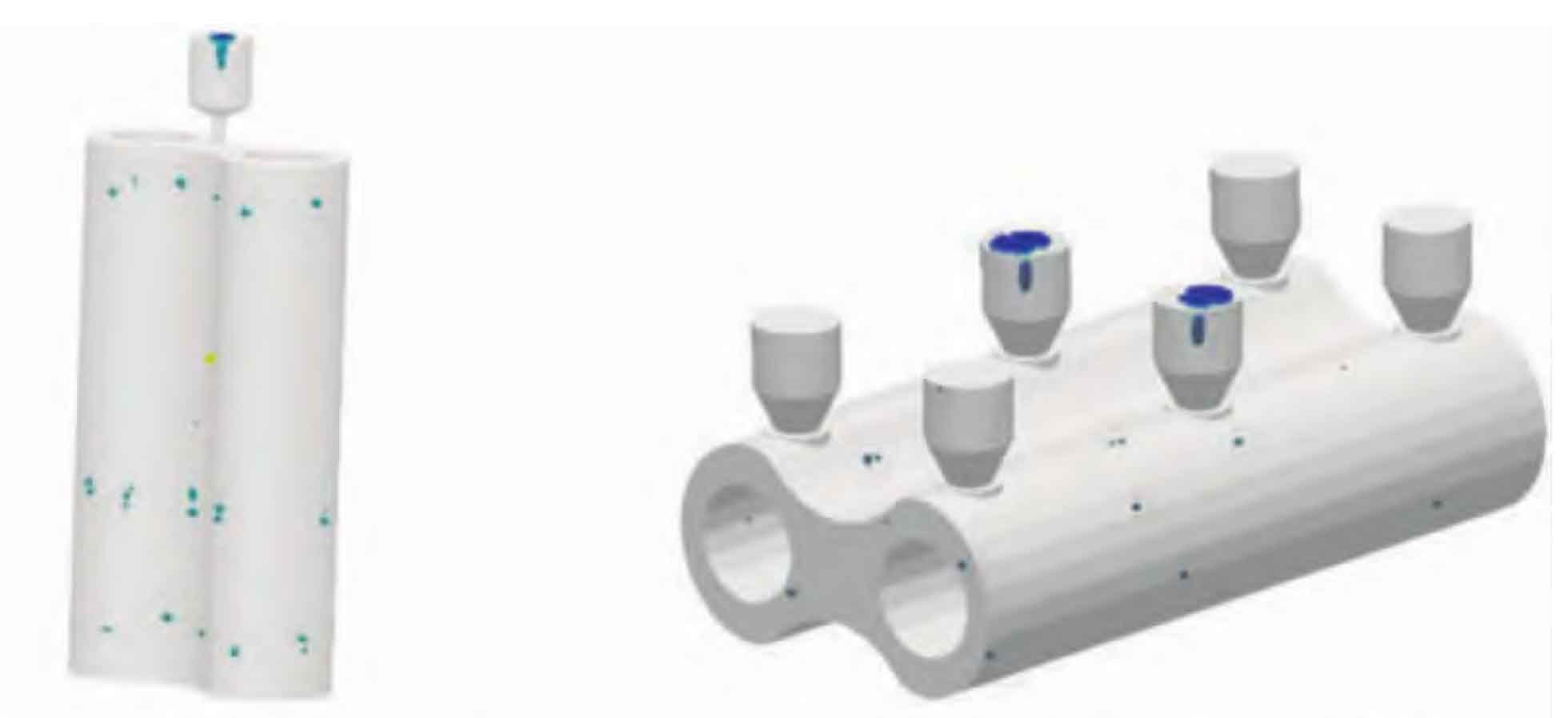
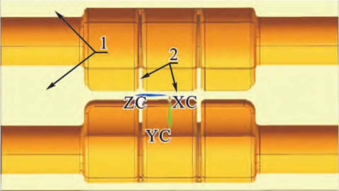
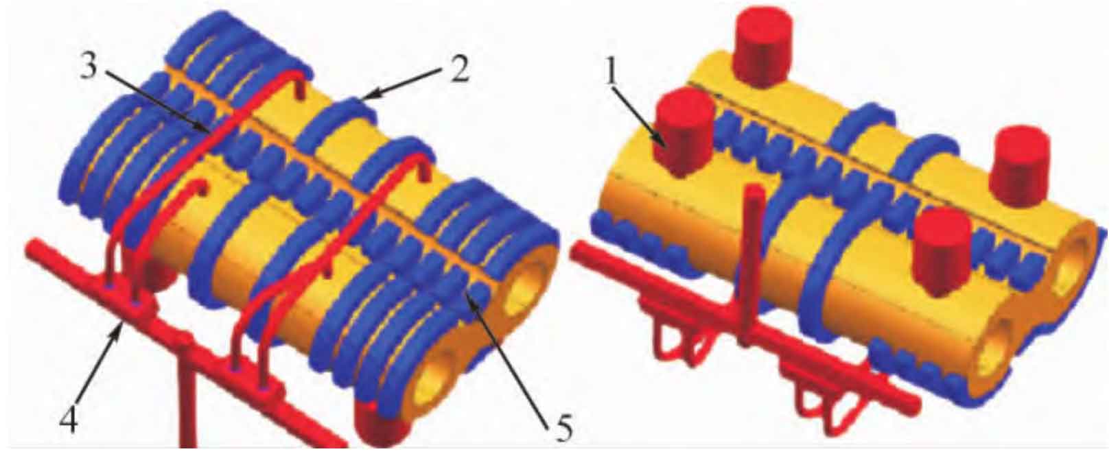
Firstly, the shrinkage distribution of solidification simulation of the two process schemes is analyzed, as shown in Figure 1. Figure 1 (a) shows the simulated shrinkage distribution of the horizontal and vertical casting process plan, and Figure 1 (b) shows the simulated shrinkage distribution of the horizontal and vertical casting process plan. Through solidification simulation of shrinkage porosity distribution, it is found that the location of shrinkage porosity defect of impeller casting is rib plate part and thicker part of impeller casting, as shown in Figure 2, where the mark 1 in Figure 2 is rib plate part of impeller casting, and the mark 2 is thicker part; Secondly, according to the solidification simulation results, the process is optimized and adjusted to solve the problem of local shrinkage and porosity of the impeller. The details are as follows: ① Four insulation risers are added to the thicker part of the cover box of the impeller casting, and the thicker part of the impeller casting is supplemented, as shown in the mark 1 in Figure 3, where the insulation riser is φ 200 mm × 200 mm, riser neck is φ 100 mm × 50 mm;② Place chills on the thicker parts of the impeller casting and the rib plate of the casting to chill the impeller casting and reduce the shrinkage tendency, as shown in the marks 2 and 5 in Figure 3; ③ Adopt low temperature rapid casting scheme, select φ The 40mm ceramic pipe increases the sectional area of the inner runner, reduces the pouring time (from 45 s to 30 s), and reduces the pouring temperature (from (1360 ± 10) ℃ to (1330 ± 10) ℃). The optimized process scheme is shown in Figure 3.


(2) Solve the problem of large plane inclusion
Inclusion is the mixture of sand inclusion and slag inclusion, mainly the loose sand from the mold cavity or gating system and the oxide slag in the molten iron. In the impeller casting process, starting from controlling the source of inclusion, the purity of molten iron and the cleanliness of the mold cavity can be improved. The methods to improve the purity of molten iron include: ① control the time from tapping to pouring to reduce the production of oxide slag, and control the time within 10 minutes; ② Before pouring, put a piece of asbestos on the molten iron surface of the ladle, which can absorb the oxide slag on the surface of the molten iron, and reduce the molten iron slag entering the tundish; ③ During pouring, when the iron level in the gating basin reaches more than 2/3 of the total height of the gating basin, the plug shall be pulled out to make the molten iron fully static and facilitate the floating of the slag in the gating basin; ④ The filter is placed in front of the inner runner to filter and block the molten iron entering the mold cavity, as shown in Figure 3, mark 4, and the specification of the filter is 120 mm × 75 mm × 20 mm, 8 pieces; ⑤ Increase the area of the inner runner, reduce the pouring time (from 45 s to 30 s), reduce the secondary oxidation slag in the molten iron mold cavity, as shown in Figure 3, mark 3, and select the diameter of the ceramic pipe φ 40 mm。
The following measures shall be taken to improve the cleanliness of the cavity: ① Clean and polish the local virtual sand or sharp sand in the cavity before closing the box to avoid bringing in molten iron during pouring; ② The inner runner is made of ceramic pipe to reduce the risk of sand washing into the mold cavity during pouring, as shown in Figure 3, Mark 3; ③ The bottom pouring system is adopted, as shown in Figure 3. The molten iron is smooth from bottom to top, and even if there is oxide slag in the molten iron or loose sand in the mold cavity, it is easy to float up and discharge through the overflow of the riser vent plate.
