1. Introduction
In the field of casting, the iron – clad sand casting process is widely used for producing gray cast iron parts, especially for components like automotive brake drums. This process offers advantages such as rapid cooling, resulting in dense casting structures and high mechanical properties. However, nitrogen porosity defects frequently occur during production, which seriously affect the quality and performance of castings. This paper aims to comprehensively analyze the causes of nitrogen porosity defects in iron – clad sand gray cast iron castings and propose effective improvement measures through in – depth research.
2. Defects in Iron – Clad Sand Gray Cast Iron Castings
2.1 Appearance and Distribution of Defects
Automotive brake drums produced by the iron – clad sand process often exhibit casting defects. These defects are mainly concentrated in the upper – corner area of the large outer circle of the brake drum. After machining 1 – 2mm, they become visible, and in severe cases, obvious holes can be seen on the casting blanks. They are distributed irregularly, densely, and continuously in a circle around the outer circle of the product, as shown in Figure 1.
| Figure 1 | Casting Defects of Brake Drum |
|---|---|
| [Insert a clear picture of the brake drum with defects here, showing the defect location and appearance] | The defects are randomly distributed on the upper – corner area of the outer circle of the brake drum. Some are small holes, and some are connected together. |
2.2 Impact of Defects on Product Quality
Nitrogen porosity defects can significantly reduce the mechanical properties of castings, such as strength and hardness. For automotive brake drums, these defects may lead to problems like reduced wear resistance and heat conductivity during use, shortening the service life of the product. In addition, the presence of defects may also affect the dimensional accuracy of the casting, causing problems in subsequent assembly processes.
3. Casting Process of Iron – Clad Sand Gray Cast Iron Castings
3.1 Melting and Molding Process
- Melting Process: The casting production adopts a medium – frequency induction furnace. The synthetic cast iron melting method uses return materials, scrap steel, and graphitized carburizers. The proportion of scrap steel added is 60% – 70%, and the rest is return materials, including gating and risering, machined iron filings, and defective products. The graphitized carburizer has a fixed C (mass fraction) greater than 98%, \(\omega(S)\leq0.5\%\), ash content \(\leq2\%\), volatile matter \(\leq1\%\), and a particle size of 1 – 5mm. The charging sequence is to first add 50% of the return materials (iron filings) at the bottom of the furnace, then add 70% of the carburizer, and then add scrap steel. During the addition of scrap steel, the remaining 30% of the carburizer is added to the furnace in two times. The iron liquid melting temperature is 1500 – 1530°C, and it is held at a high temperature of 1530 – 1550°C for 5 minutes with repeated slag skimming. The tapping temperature of the iron liquid is 1490 – 1530°C, and when tapping, \(75\%\) ferrosilicon is used for inoculation treatment. The pouring temperature of the last piece is not lower than 1360°C, and the pouring time of the whole ladle does not exceed 15 minutes.
- Molding Process: The old sand used is regenerated coated sand, and the new sand is Inner Mongolia Tongliao sand with a particle size of 70 – 140 mesh. The new sand addition amount is 5% – 20%, and the rest is regenerated sand. The coated sand adopts a thermal regeneration process, and its main process flow includes old sand crushing, screening, magnetic separation, thermal regeneration, micro – powder removal, cooling, storage, and inspection. The coated sand has the following performance indicators: normal – temperature tensile strength \(\geq2.5MPa\), normal – temperature bending strength \(\geq6MPa\), hot – state tensile strength \(\geq1.3MPa\), hot – state bending strength \(\geq3.8MPa\), ignition loss \(\leq2.6\%\), gas evolution \(\leq20\) mL, and melting point of 95 – 110°C.
| Melting and Molding Process Parameters | Details |
|---|---|
| Melting Furnace Type | Medium – frequency induction furnace |
| Raw Materials for Melting | Return materials, scrap steel, graphitized carburizer |
| Scrap Steel Proportion | 60% – 70% |
| Carburizer Specifications | Fixed C > 98%, \(\omega(S)\leq0.5\%\), ash \(\leq2\%\), volatile \(\leq1\%\), 1 – 5mm |
| Melting Temperature Range | 1500 – 1530°C (melting), 1530 – 1550°C (holding) |
| Tapping Temperature Range | 1490 – 1530°C |
| Inoculant | \(75\%\) ferrosilicon |
| Pouring Temperature Requirement | Not lower than 1360°C (last piece) |
| Pouring Time Limit | Not more than 15 minutes (whole ladle) |
| New Sand Type | Inner Mongolia Tongliao sand |
| New Sand Particle Size | 70 – 140 mesh |
| New Sand Addition Amount | 5% – 20% |
| Coated Sand Regeneration Process | Old sand crushing, screening, magnetic separation, thermal regeneration, micro – powder removal, cooling, storage, inspection |
| Coated Sand Performance Indicators | Normal – temperature tensile \(\geq2.5MPa\), normal – temperature bending \(\geq6MPa\), hot – state tensile \(\geq1.3MPa\), hot – state bending \(\geq3.8MPa\), ignition loss \(\leq2.6\%\), gas evolution \(\leq20\) mL, melting point 95 – 110°C |
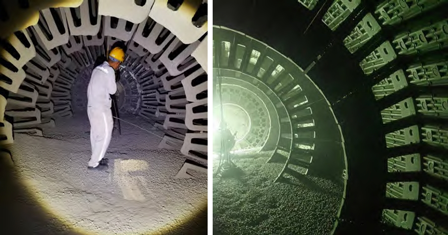
3.2 Pouring System
The pouring system of the iron – clad sand brake drum casting is shown in Figure 2. It adopts an intermediate top – pouring method. The pouring cup is funnel – shaped, and the pressure angle formed by the top of the cup and the largest outer – circle plane of the casting is not less than 40°. A 15PPI ceramic filter is placed in the pouring cup to filter the iron liquid. A pouring well with a radius of not less than R50 is set below the pouring cup to buffer the iron water entering the cavity and avoid high – degree turbulence. It uses a semi – closed pouring system, and \(\sum S_{inner}:\sum S_{runner}:\sum S_{sprue}=1:4.17:2.04\). According to the product structure, 4 or 5 inner gates are set, and the cross – sectional area of a single inner gate is not less than \(240mm^{2}\). The pouring time of a single mold of the casting does not exceed 25s. Two stress grooves are set on each side of the upper and lower parts of the inner gate to break when removing the pouring system and protect the casting body from damage. The width of the runner is the same as that of the inner gate, and the thickness is determined according to the flange wall thickness of the casting, generally set at 1.25 times the flange wall thickness to ensure that the molten metal flows into the inner gate smoothly and stores the low – temperature molten metal containing gas and slag at the beginning of pouring to play a slag – blocking role.
| Figure 2 | Casting Gating System of Sand – Covered Brake Drum of Iron Mould |
|---|---|
| [Insert a clear picture of the pouring system here, showing the structure of the pouring cup, runner, inner gate, etc.] | The pouring system is well – designed to ensure the smooth flow of iron liquid and the exclusion of gas and slag. |
| Pouring System Parameters | Details |
|---|---|
| Pouring Method | Intermediate top – pouring |
| Pouring Cup Shape | Funnel – shaped |
| Pressure Angle of Pouring Cup | Not less than 40° |
| Filter in Pouring Cup | 15PPI ceramic filter |
| Pouring Well Radius | Not less than R50 |
| Pouring System Type | Semi – closed |
| Gate Ratio (\(\sum S_{inner}:\sum S_{runner}:\sum S_{sprue}\)) | 1:4.17:2.04 |
| Number of Inner Gates | 4 or 5 |
| Cross – Sectional Area of Single Inner Gate | Not less than \(240mm^{2}\) |
| Pouring Time Limit (Single Mold) | Not more than 25s |
| Stress Grooves of Inner Gate | Two on each side of upper and lower parts |
| Runner Width and Thickness | Width same as inner gate, thickness 1.25 times flange wall thickness |
4. Analysis of Nitrogen Porosity Defects
4.1 EDS Energy – Dispersive Spectroscopy Analysis
An EDS energy – dispersive spectrometer was used to analyze the defects and their surroundings. From the defect surface scan diagram (Figure 3), it can be seen that the defect area has dendritic structures, and the defect shape is irregular, perpendicular to the casting surface and penetrating 2 – 5mm into the casting. The main elements in the defect area of the casting are C, N, Fe, O, and Si. Among them, the contents of N, C, and Fe are relatively high, and they are segregated, with different contents inside and outside the defect. The detection results show that the C element is mainly concentrated inside the defect, while the N element is mainly distributed in the surrounding area of the defect and is relatively uniformly distributed. There is a continuous or discontinuous graphite film precipitated inside the defect, which is connected to the decarburized matrix tissue around it. This is a typical nitrogen porosity defect caused by high N content.
| Figure 3 | Defect Surface Scan Diagram |
|---|---|
| [Insert a clear picture of the defect surface scan here, showing the dendritic structure and the distribution of elements] | The scan diagram clearly shows the internal structure of the defect and the distribution characteristics of elements. |
| Element Content in Defect (Mass Fraction, %) | N | C | Fe | O | Si |
|---|---|---|---|---|---|
| Value | 49.5 | 28.58 | 12.71 | 8.87 | 0.34 |
4.2 Formation Mechanism of Nitrogen Porosity
Nitrogen in the iron liquid is dissolved in iron to form an interstitial solid solution. During the solidification process of the iron liquid, as the temperature decreases, the solubility of nitrogen also decreases. During the solidification of the iron liquid, the solubility of nitrogen in the first – solidified iron liquid decreases, causing the nitrogen content in the later – solidified iron liquid to gradually increase. When the nitrogen content in the iron liquid exceeds its solubility, nitrogen gas is precipitated. Due to the fast cooling speed of the iron – clad sand casting process, the surface iron liquid solidifies and crusts quickly, and the nitrogen gas cannot be discharged smoothly, resulting in nitrogen porosity defects.
4.3 Causes of Nitrogen Porosity
The main reason for the nitrogen porosity is the excessive \(\omega(N)\) in the iron liquid. For iron – clad sand gray cast iron brake drum castings, when the \(\omega(N)\) in the iron liquid exceeds 120ppm, nitrogen porosity is likely to occur. The sources of nitrogen mainly include the following three aspects:
- Scrap Steel: In the melting of synthetic cast iron, a high proportion of scrap steel is used. For some common carbon steels and high – manganese steels with high demand in gray cast iron casting, their \(\omega(N)\) is relatively high. For example, the \(\omega(N)\) of low – carbon steel is about 40 – 60ppm, that of rebar is about 90ppm, and that of guide – rail steel is about 110 – 120ppm.
- Carburizer: Different types of carburizers have different nitrogen contents. The \(\omega(N)\) of coal – based carburizers is about 2000 – 7000ppm (i.e., 0.2% – 0.7%); that of ordinary calcined petroleum coke carburizers is generally about 1000ppm; that of high – temperature calcined petroleum coke carburizers is 300 – 500ppm; and that of graphitized carburizers is not more than 300ppm.
- Coated Sand: Coated sand is mainly composed of original sand, regenerated sand, thermoplastic phenolic resin, curing agent, and additives. The widely used curing agent in the industry is hexamethylenetetramine. When hexamethylenetetramine is heated above 230°C, it will decompose in large quantities. Therefore, during the heating and curing of coated sand and the pouring process, a large amount of \(NH_{3}\) will be volatilized.
| Nitrogen Sources | Nitrogen Content Range |
|---|---|
| Scrap Steel (Low – carbon Steel) | 40 – 60ppm |
| Scrap Steel (Rebar) | 90ppm |
| Scrap Steel (Guide – rail Steel) | 110 – 120ppm |
| Coal – based Carburizer | 2000 – 7000ppm (0.2% – 0.7%) |
| Ordinary Calcined Petroleum Coke Carburizer | About 1000ppm |
| High – temperature Calcined Petroleum Coke Carburizer | 300 – 500ppm |
| Graphitized Carburizer | Not more than 300ppm |
| Coated Sand (Calculated from Resin and Curing Agent) | 0.12% – 0.15% (about 1200 – 1500ppm) |
Through the detection of the nitrogen content in the iron liquid, the measured value is 71.7ppm, which is not enough to cause nitrogen porosity defects in the casting. Therefore, the influence of excessive nitrogen content in the iron liquid on nitrogen porosity defects can be excluded. In the production of coated sand, the resin addition amount accounts for 2% – 2.5% of the mass fraction of the original sand, and hexamethylenetetramine accounts for 15% of the resin mass. Since N accounts for 40% of the mass of hexamethylenetetramine, through calculation, the \(\omega(N)\) in the coated sand is about 0.12% – 0.15% (i.e., 1200 – 1500ppm), which is much higher than 120ppm, and it is likely to cause nitrogen porosity defects in the casting.
5. Improvement Measures
5.1 Improvement of Coated Sand Quality
- Change of Suppliers: Replace the suppliers of coated sand raw materials, especially to ensure the quality of thermoplastic phenolic resin and hexamethylenetetramine. High – quality raw materials can reduce the nitrogen – containing impurities in the coated sand, thereby reducing the risk of nitrogen porosity.
- Adjustment of New Sand Addition: Increase the addition amount of new sand in the coated sand ratio from the current 5% – 20% to 20% – 40%. This can reduce the residual nitrogen content in the regenerated sand. New sand has a lower nitrogen content, and increasing its proportion can effectively dilute the nitrogen in the coated sand and reduce the nitrogen porosity risk.
- Separate Management of Recycled Sand: Distinguish and manage the recycled old sand from the shell – molding line and the iron – molding line. Since the performance requirements, sand particle sizes, and new sand addition amounts of the coated sand for the two production lines are different, mixing the recycled sand will lead to process problems. Separated management can ensure the stability of the coated sand quality for each production line.
| Coated Sand Quality Improvement Measures | Details |
|---|---|
| Supplier Change | Replace suppliers of thermoplastic phenolic resin and hexamethylenetetramine |
| New Sand Addition Adjustment | Increase from 5% – 20% to 20% – 40% |
| Recycled Sand Management | Separate management of shell – molding and iron – molding line recycled sand |
5.2 Improvement of Production Process
- Addition of Exhaust Plugs: Add exhaust plugs to the mold, especially in the bottom and corner areas to increase the exhaust channels. This is beneficial for the discharge of gas during the curing of the coated sand and also conducive to the filling of the coated sand, improving the sand – shooting quality.
- Adjustment of Mold and Iron – Mold Temperatures: Since hexamethylenetetramine in the coated sand decomposes in large quantities at 230°C, and the coating – sand curing temperature of the iron – clad sand process is generally 220 – 240°C, the mold temperature is set at 230 – 250°C, and the iron – mold temperature is set at 240 – 280°C to accelerate the gas evolution of the coated sand.
- Increase of Exhaust Channels and Extension of Curing Time: Increase the number of exhaust channels of the iron mold from 8 to 20 to facilitate the discharge of the gas volatilized from the coated sand in the cavity. At the same time, extend the time from curing and closing the mold to the start of pouring from 10 minutes to not less than 20 minutes, which is conducive to the discharge of gas.
- Adjustment of Pouring Temperature: Appropriately increase the pouring temperature to reduce the viscosity of the iron liquid. This is beneficial for the gas invading the iron liquid to float up, thereby reducing the formation of casting porosity defects.
| Production Process Improvement Measures | Details |
|---|---|
| Addition of Exhaust Plugs | Install exhaust plugs in mold bottom and corners; enhance exhaust channels; improve sand – shooting quality |
| Temperature Adjustment | Set mold temp. at 230 – 250°C, iron – mold temp. at 240 – 280°C to speed up coated – sand gas evolution |
| Exhaust Channels and Curing Time | Increase iron – mold exhaust channels from 8 to 20; extend curing – to – pouring time to ≥ 20 min for better gas discharge |
| Pouring Temperature Adjustment | Raise pouring temp. to lower iron – liquid viscosity, helping gas float and reducing porosity |
6. Implementation and Effect of Improvement Measures
6.1 Implementation Process
After formulating the improvement measures, they were gradually implemented in the production process. First, the procurement department worked with new coated – sand raw material suppliers to ensure the supply of high – quality materials. The production department adjusted the mixing ratio of coated sand on – site, increasing the proportion of new sand. Meanwhile, workers installed exhaust plugs in the molds as required, and the temperature control systems of molds and iron molds were adjusted to the specified temperature ranges. The number of exhaust channels in iron molds was increased, and the time between curing and pouring was strictly controlled.
6.2 Effect of Improvement
After implementing these improvement measures, continuous production of more than 100,000 products was carried out. During this period, no nitrogen porosity defects were found in the products. This indicates that the improvement measures are effective in solving the nitrogen porosity problem in iron – clad sand gray cast iron castings. The quality of the castings has been significantly improved, and the mechanical properties such as strength and hardness have also met the requirements, which greatly enhances the competitiveness of products in the market.
7. Conclusion
Nitrogen porosity defects in iron – clad sand gray cast iron castings are mainly caused by excessive nitrogen content in the iron liquid, with the main sources being scrap steel, carburizers, and coated sand. Through EDS energy – dispersive spectroscopy analysis, the formation mechanism and specific causes of defects can be accurately determined. By improving the quality of coated sand, such as changing suppliers, adjusting the new – sand addition ratio, and separating recycled – sand management, and optimizing the production process, including adding exhaust plugs, adjusting temperatures, increasing exhaust channels, and adjusting the pouring temperature, the nitrogen porosity defects can be effectively reduced. The successful implementation of these improvement measures not only improves the quality of castings but also provides valuable experience for similar casting processes. Future research can further explore the impact of other factors on casting quality and continuously optimize the casting process to achieve higher – quality casting production.