
I developed a complete water glass sand casting process for a water valve used in fluid control systems. The valve is a critical component because its sealing performance, dimensional accuracy, and internal soundness directly influence the stability of the entire fluid circuit. I focused on a practical sand casting route that balances casting quality, production cost, and small-batch flexibility. The valve has an overall envelope of approximately 480 mm × 448 mm × 250 mm, four connected ports, and an internal hollow flow channel. Several connection faces and sealing faces require good surface quality and controlled dimensional precision. The material I selected is ductile iron because it provides higher strength and hardness than aluminum alloys while also offering low cost and good corrosion resistance. The casting must be free from gas porosity, slag inclusion, shrinkage porosity, and other harmful defects, and it must receive an aging treatment before final service.
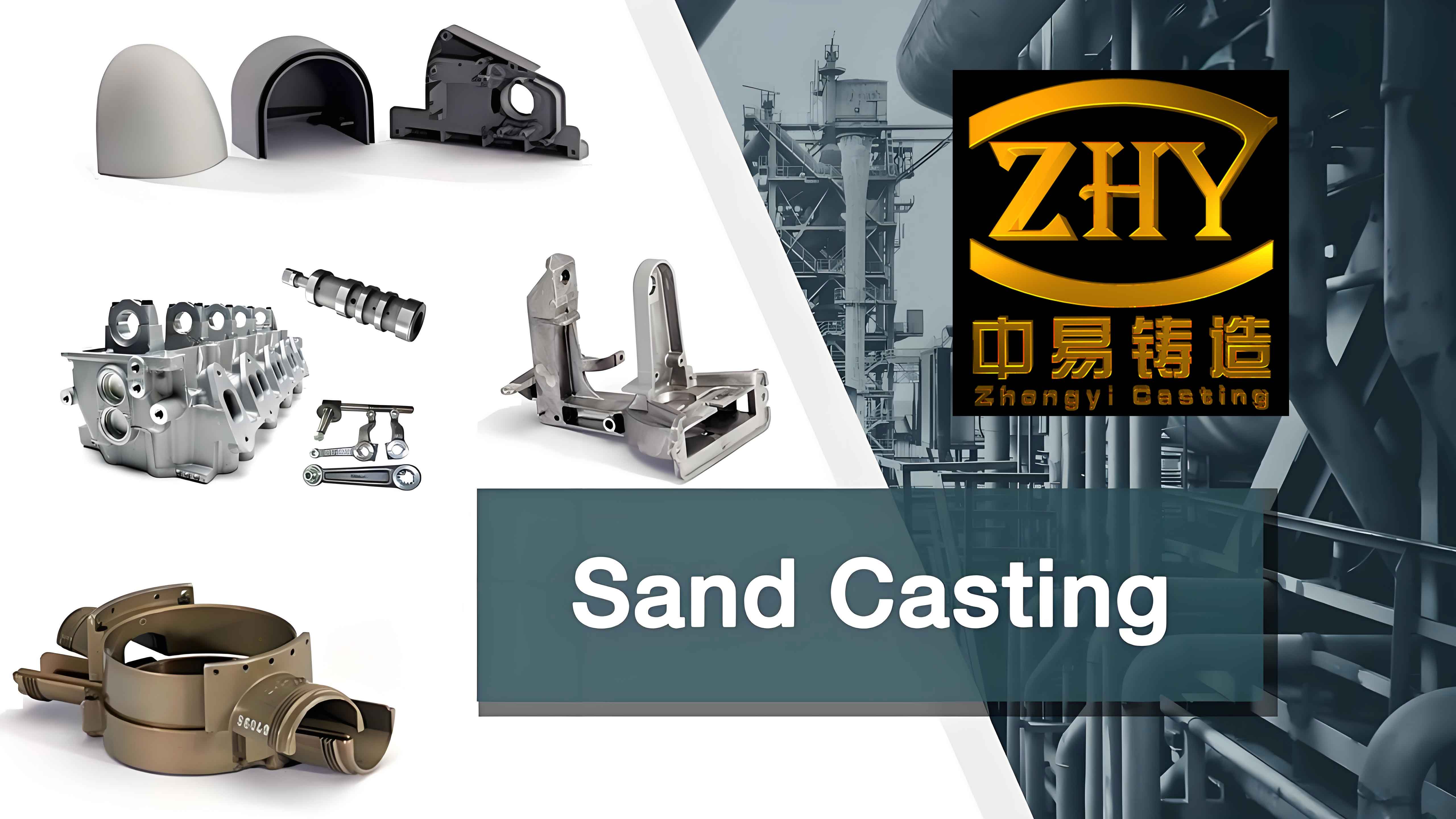
I treated the water valve as a sand casting component with multiple thermal masses, several cores, and a strong requirement for progressive solidification. The sand casting process must deliver a sound pressure-bearing body, stable sealing surfaces, and a repeatable molding cycle. Because the production volume is small, I avoided expensive permanent mold tooling and selected water glass sand casting. This sand casting method is adaptable, simple to operate, and suitable for single-piece or small-batch production. It also provides good refractory performance and adequate mold strength when the water glass binder is properly controlled.
1. Component Requirements and Casting Design Inputs
I began by converting the water valve design into casting engineering inputs. The external shape, internal flow passages, sealing faces, and connection interfaces all influence the parting plane, core design, gating system, and feeding strategy. I reviewed the wall thickness distribution and identified the heavy sections that would solidify last. I also identified the thin sections that would cool quickly and might cause incomplete filling if the pouring temperature or gating design were poor. For a sand casting of this type, the main design targets are complete filling, directional solidification, adequate feeding, and clean surface formation.
| Design input | Value or requirement | Effect on sand casting |
|---|---|---|
| Overall envelope | 480 mm × 448 mm × 250 mm | Determines flask size, sand volume, and mold handling |
| Main features | Four ports and internal hollow flow channel | Requires sand cores and controlled core positioning |
| Critical faces | Connection faces and sealing faces | Needs machining allowance and stable surface quality |
| Material | Ductile iron | Provides strength, hardness, corrosion resistance, and castability |
| Production batch | Small batch | Favors water glass sand casting over high-cost tooling |
| Defect limits | No gas porosity, slag inclusion, or harmful shrinkage | Requires clean melting, good gating, and effective risering |
| Post-processing | Aging treatment | Relieves residual stress and stabilizes dimensions |
I used the thermal modulus concept to compare the cooling behavior of different regions. The thermal modulus of a casting section can be written as
$$M = \frac{V}{A}$$
where \(M\) is the thermal modulus, \(V\) is the volume of the section, and \(A\) is the heat-dissipating surface area. Regions with a larger thermal modulus solidify more slowly. I identified the largest port outlet and the upper part of the thickest connected section as likely hot spots. This prediction guided the riser location and the gating layout. In sand casting, the mold and core materials also affect heat transfer, so I did not rely only on geometric modulus. I combined geometry, sand properties, and simulation results to refine the design.
2. Material Selection and Metallurgical Design
I selected ductile iron because it combines castability with mechanical performance. Compared with aluminum alloys, ductile iron offers higher strength and hardness. It also has favorable corrosion resistance and lower raw material cost for this class of water valve. The graphite nodules in ductile iron reduce stress concentration and improve toughness. However, ductile iron is sensitive to melting practice, inoculation, and magnesium treatment. Poor control can cause graphite degeneration, slag inclusion, gas porosity, or shrinkage defects. Therefore, I specified a narrow chemical composition range and strict pouring practice.
| Element | Target range (wt.%) | Function in ductile iron |
|---|---|---|
| C | 3.50–3.80 | Promotes graphite formation and castability |
| Si | 2.20–2.70 | Improves inoculation and controls matrix structure |
| Mn | 0.20–0.50 | Controls pearlite and improves strength |
| P | ≤ 0.05 | Minimizes brittleness and segregation |
| S | ≤ 0.02 | Reduces spheroidization inhibition and slag |
| Mg | 0.03–0.06 | Promotes spheroidal graphite |
| RE | 0.02–0.05 | Assists desulfurization and spheroidization |
| Cu | 0.20–0.50 | Optional pearlite stabilizer |
| Fe | Balance | Base matrix |
I calculated the carbon equivalent to estimate the freezing range and shrinkage tendency. The carbon equivalent can be expressed as
$$CE = C + \frac{Si}{3} + \frac{P}{2}$$
I targeted a carbon equivalent near the eutectic range to improve fluidity and reduce shrinkage. A properly inoculated ductile iron can fill thin sand casting sections while maintaining a sound matrix. I also considered the volumetric contraction during liquid cooling, eutectic solidification, and solid-state cooling. The total shrinkage can be approximated by
$$\Delta V = V \beta \Delta T$$
where \(\Delta V\) is the volume change, \(V\) is the initial volume, \(\beta\) is the volumetric contraction coefficient, and \(\Delta T\) is the temperature change. This relationship helps explain why risers must supply liquid metal to isolated hot spots. In a water glass sand casting, the mold is rigid, so the casting cannot easily compensate for internal contraction. The gating and riser system must therefore provide enough feed metal before the hot spot solidifies.
| Property | Target | Verification method |
|---|---|---|
| Tensile strength | ≥ 400 MPa | Tensile test on cast coupon |
| Yield strength | ≥ 250 MPa | Tensile test |
| Elongation | ≥ 12% | Tensile test |
| Hardness | 170–230 HBW | Brinell hardness test |
| Microstructure | Nodular graphite with ferrite-pearlite matrix | Metallographic examination |
| Internal soundness | No harmful shrinkage or gas porosity | Simulation and production inspection |
3. Sand Casting Method and Water Glass Sand System
I chose water glass sand casting as the production method. This sand casting route is especially suitable for small-batch water valve production because it has strong adaptability and simple process control. Water glass, also known as sodium silicate, acts as the binder. When mixed with silica sand and a hardening agent, it creates a mold and core with sufficient strength for pouring. The sand casting mold can be used after proper hardening, and the core can be shaped to form the internal hollow flow channel of the valve. I selected this method because it avoids the high tooling cost of permanent molds and the complexity of more advanced sand casting systems.
| Sand mixture component | Approximate proportion | Purpose |
|---|---|---|
| Silica sand | 100 parts by weight | Refractory aggregate and mold body |
| Water glass binder | 6–8% of sand weight | Provides green and hardened strength |
| Hardening agent | 0.5–1.5% of sand weight | Accelerates gelation and hardening |
| Water | Adjustable | Controls workability and coating uniformity |
| Additives | 0–2% | Improves collapsibility or surface finish |
I defined the binder ratio as
$$B = \frac{m_{binder}}{m_{sand}} \times 100\%$$
where \(B\) is the binder mass percentage, \(m_{binder}\) is the mass of water glass, and \(m_{sand}\) is the mass of silica sand. A binder ratio that is too low produces weak molds and cores. A binder ratio that is too high improves strength but may reduce collapsibility and increase cost. I therefore kept the binder within a controlled range and verified the mold hardness before pouring. The sand casting quality depends strongly on sand mixing, compaction, and hardening uniformity.
| Sand property | Target range | Reason |
|---|---|---|
| Green compressive strength | 0.08–0.15 MPa | Enough handling strength before hardening |
| Hardened compressive strength | ≥ 1.5 MPa | Withstands pouring pressure and erosion |
| Permeability | 100–180 | Allows gas escape from mold and core |
| Moisture content | Controlled and uniform | Prevents gas defects and weak zones |
| Loss on ignition | Low and stable | Reduces gas generation during pouring |
| Surface stability | Good coating adhesion | Improves casting surface finish |
I also considered the environmental and reclamation aspects of water glass sand casting. Used sand can be mechanically or thermally reclaimed, which reduces waste and raw material consumption. Because the binder is inorganic, the sand casting process can be managed with relatively low organic emissions compared with some organic binder systems. However, water glass sand can be difficult to collapsible if the binder addition is excessive, so I balanced strength with shakeout performance.
4. Pattern, Parting Plane, and Molding Layout
I examined the symmetry of the water valve and selected the central horizontal plane as the parting plane. The valve is approximately symmetric about this plane, and placing the parting plane there keeps the mold height lower. A lower mold height reduces sand volume, improves compaction uniformity, and simplifies molding. I divided the sand mold into an upper mold and a lower mold. The internal cavity of the valve was formed by sand cores. This arrangement is a standard and effective approach for sand casting of hollow valve bodies.
| Molding decision | Selection | Benefit |
|---|---|---|
| Parting plane | Central horizontal symmetry plane | Lower mold height and simpler pattern layout |
| Mold type | Upper and lower sand mold | Easy core placement and gating access |
| Internal cavity | Sand cores | Forms the hollow flow channel |
| Mold layout | One mold with two castings | Improves productivity and sand utilization |
| Gating location | Parting plane for horizontal runners | Convenient pattern making and cleaning |
| Riser location | Top of largest port outlet | Feeds the last solidifying hot spot |
I included pattern allowances for machining, draft, and shrinkage. The mold height can be estimated by
$$h_{mold} = h_{part} + h_{core print} + h_{clearance}$$
where \(h_{mold}\) is the total mold cavity height, \(h_{part}\) is the casting height, \(h_{core print}\) is the core print height, and \(h_{clearance}\) is the required clearance for sand compaction and closing. I kept the core prints robust enough to prevent core shift during pouring. Core shift is a common problem in sand casting of hollow parts because the buoyancy of the liquid metal can lift or displace the core. A stable core print and proper chaplet support, if needed, reduce this risk.
| Allowance type | Typical value | Reason |
|---|---|---|
| Machining allowance | 2–5 mm on sealing faces | Removes surface defects and achieves tolerance |
| Draft angle | 1–2 degrees | Facilitates pattern removal from sand |
| Shrinkage allowance | 0.8–1.2% for ductile iron | Compensates solid contraction |
| Core print clearance | 0.2–0.5 mm | Allows core placement without damage |
| Closing clearance | Controlled by flask alignment | Prevents mold shift and flash |
5. Gating System Design
I designed the gating system to deliver clean metal quickly and smoothly into the mold cavity. I placed the horizontal runners at the parting plane and used four runners positioned around the water valve. A single sprue was located at the intersection of the four runners. This arrangement allows the metal to enter the mold from multiple directions and reduces the distance that the liquid must travel. The goal was to fill the sand casting before the metal loses too much superheat and to avoid turbulent flow that could entrain air or wash the sand mold.
| Gating element | Design choice | Function |
|---|---|---|
| Sprue | One vertical sprue at the runner intersection | Delivers metal from pouring basin to runners |
| Runner | Four horizontal runners at the parting plane | Distributes metal to different valve positions |
| Ingate | Multiple ingates feeding the valve body | Controls entry velocity and filling pattern |
| Pouring basin | Designed to absorb pouring impact | Reduces turbulence and slag entrainment |
| Slag trap | Integrated into runner path | Helps prevent slag from entering the cavity |
I estimated the pouring time using an empirical relationship:
$$t = K \sqrt{G}$$
where \(t\) is the pouring time, \(K\) is an empirical coefficient that depends on alloy and casting geometry, and \(G\) is the casting mass. For ductile iron sand casting, the pouring time must be long enough to avoid excessive turbulence but short enough to prevent premature freezing. I also considered the gating ratio:
$$A_s : A_r : A_g = 1 : 2 : 4$$
where \(A_s\) is the sprue cross-sectional area, \(A_r\) is the runner cross-sectional area, and \(A_g\) is the ingate cross-sectional area. A properly proportioned gating system provides a controlled pressure drop and promotes smooth filling. The flow velocity through each gate can be estimated by
$$v = \frac{Q}{A}$$
where \(v\) is the flow velocity, \(Q\) is the volumetric flow rate, and \(A\) is the cross-sectional area. I kept the ingate velocity within a range that minimizes sand erosion and air entrainment. The Reynolds number was used as a qualitative check:
$$Re = \frac{\rho v D}{\mu}$$
where \(Re\) is the Reynolds number, \(\rho\) is the density, \(v\) is the flow velocity, \(D\) is the hydraulic diameter, and \(\mu\) is the dynamic viscosity. A lower Reynolds number generally indicates a more laminar flow condition. In sand casting, smooth flow is important because turbulence can oxidize the metal and produce gas defects.
| Gating parameter | Designed value | Rationale |
|---|---|---|
| Number of runners | 4 | Provides balanced filling around the valve |
| Sprue location | Center of runner intersection | Even distribution and short flow path |
| Runner location | Parting plane | Easy molding and cleaning |
| Gating ratio | 1 : 2 : 4 | Promotes controlled filling and slag control |
| Pouring time target | Approximately 5.2 s | Balances complete filling and freezing risk |
| Flow condition | Smooth, non-turbulent | Reduces gas porosity and sand erosion |
6. Riser Design and Feeding Strategy
I predicted that the last solidifying region would be near the top of the largest port outlet. If this region solidifies without sufficient liquid feed, it can form shrinkage porosity or shrinkage cavities. I therefore placed a riser at that location. The riser acts as a reservoir of liquid metal and feeds the hot spot during solidification. In sand casting, riser design is one of the most important factors for internal soundness because the mold does not collapse to compensate for shrinkage.
I used the modulus method to size the riser. The modulus of the riser and the casting section are
$$M_r = \frac{V_r}{A_r}$$
$$M_c = \frac{V_c}{A_c}$$
where \(M_r\) is the riser modulus, \(V_r\) is the riser volume, \(A_r\) is the riser surface area, \(M_c\) is the casting modulus, \(V_c\) is the casting volume, and \(A_c\) is the casting surface area. For effective feeding, the riser modulus should be larger than the casting modulus:
$$M_r \geq 1.2 M_c$$
I also shaped the riser to minimize heat loss and to keep the feeding channel open. A cylindrical riser volume can be approximated by
$$V_r = \frac{\pi D^2}{4} H$$
where \(D\) is the riser diameter and \(H\) is the riser height. I selected a riser size that would remain liquid long enough to feed the hot spot without creating an excessively large contact area that could cause surface defects. The riser neck was designed to freeze after the feeding path was no longer needed but before the riser became isolated.
| Riser parameter | Design selection | Function |
|---|---|---|
| Location | Top of largest port outlet | Feeds the predicted last solidification zone |
| Type | Cylindrical top riser | Provides a large feeding reservoir |
| Modulus ratio | \(M_r \geq 1.2 M_c\) | Ensures the riser remains liquid longer |
| Neck design | Tapered and short | Maintains feeding and easy removal |
| Insulation | Optional exothermic sleeve | Extends riser solidification time |
| Yield impact | Controlled riser volume | Balances feeding and material efficiency |
7. Numerical Simulation Setup
I used a finite-volume casting simulation package to verify the filling and solidification behavior of the sand casting process. The simulation allowed me to examine the metal flow front, temperature distribution, solid fraction evolution, and defect probability. I imported the casting geometry, including the gating system, riser, sand mold, and sand cores. I then assigned thermophysical properties to the casting alloy, mold, and core materials. The simulation setup is summarized below.
| Simulation input | Value or model | Purpose |
|---|---|---|
| Casting alloy | Ductile iron | Defines density, viscosity, conductivity, and latent heat |
| Mold material | Water glass silica sand | Defines heat transfer from casting to mold |
| Core material | Water glass sand core | Controls internal cooling and hot spot formation |
| Initial casting temperature | 1330 °C | Represents the pouring temperature |
| Initial mold temperature | Preheated to reduce thermal shock | Reduces temperature gradient and gas defects |
| Heat transfer coefficient | Interface-dependent | Controls heat flow between casting and sand |
| Mesh type | Finite-volume mesh with local refinement | Resolves thin sections and gate details |
The energy equation used in the simulation can be written as
$$\rho c_p \left( \frac{\partial T}{\partial t} + v \cdot \nabla T \right) = \nabla \cdot (k \nabla T) + q$$
where \(\rho\) is density, \(c_p\) is specific heat, \(T\) is temperature, \(t\) is time, \(v\) is velocity, \(k\) is thermal conductivity, and \(q\) is a source term that accounts for latent heat release. During solidification, the latent heat is released over a temperature interval. I used the solid fraction to track the progress of freezing:
$$f_s = \frac{T_L – T}{T_L – T_S}$$
where \(f_s\) is the solid fraction, \(T_L\) is the liquidus temperature, \(T\) is the local temperature, and \(T_S\) is the solidus temperature. When \(f_s\) reaches one, the region is fully solid. When \(f_s\) is between zero and one, the region is in the mushy zone and may be sensitive to shrinkage and feeding problems.
I used the Niyama criterion as a defect indicator:
$$N_y = \frac{G}{\sqrt{R}}$$
where \(N_y\) is the Niyama criterion, \(G\) is the temperature gradient, and \(R\) is the cooling rate. Regions with a low Niyama value have a higher probability of shrinkage porosity. I combined this criterion with the solidification sequence and hot spot location to evaluate the riser design. The simulation results helped me confirm whether the riser was large enough and whether the gating system provided a smooth fill pattern.
8. Filling Simulation and Flow Behavior
I simulated the filling process and examined the flow front at several times. The metal entered through the sprue, distributed into the four horizontal runners, and then rose from the bottom of the casting toward the middle and upper regions. The last filling locations were the top of the casting and the riser. This bottom-to-top filling pattern is desirable because it reduces splashing and helps displace air from the mold cavity. The flow remained relatively smooth, and I did not observe severe turbulence or premature freezing in the thin sections.
| Filling stage | Approximate time | Observation |
|---|---|---|
| Initial metal entry | 0.0–1.5 s | Metal fills sprue and begins to distribute through runners |
| Lower casting fill | 1.5–3.5 s | Metal rises from the bottom and fills lower ports |
| Upper casting fill | 3.5–5.2 s | Metal reaches the upper sections and riser |
| Final fill | Approximately 5.2 s | Top and riser are the last regions to fill |
| Flow character | Throughout filling | Smooth and stable, without severe turbulence |
The filling time can be approximated by summing the volume increments divided by the local flow rate:
$$t_f = \sum \frac{\Delta V_i}{Q_i}$$
where \(t_f\) is the total filling time, \(\Delta V_i\) is a volume increment, and \(Q_i\) is the local volumetric flow rate. The simulated filling time of about 5.2 s was consistent with the designed gating system. This filling time allowed the metal to reach the extremities before solidification became restrictive, while avoiding an excessively long pour that could cause sand erosion or gas defects.
9. Solidification Simulation and Defect Prediction
After filling, I analyzed the solidification sequence. The three interface regions and the outermost surfaces of the water valve began to solidify first because they contacted the sand cores and mold surfaces. These regions had a high heat-dissipating area and a relatively small thermal modulus. The thicker regions, such as the adjacent interfaces between the two castings and the intersection of the runners and sprue, solidified later. The riser and runners provided liquid metal to the late-solidifying regions.
| Solidification stage | Region | Behavior |
|---|---|---|
| Early solidification | Thin outer surfaces and core-contact areas | Rapid cooling because of high surface-to-volume ratio |
| Intermediate solidification | Moderate wall sections and port walls | Controlled cooling with progressive freezing |
| Late solidification | Thick port connections and runner-sprue intersection | Requires feed metal from riser and runners |
| Last solidification | Top of largest port outlet and riser | Riser remains liquid and feeds the hot spot |
| Final stage | Riser neck solidifies | Ends feeding after casting is sound |
The solidification time can be estimated by Chvorinov’s rule:
$$t_s = B \left(\frac{V}{A}\right)^n$$
where \(t_s\) is the solidification time, \(B\) is a constant that depends on the alloy and mold, \(V/A\) is the thermal modulus, and \(n\) is an exponent typically close to 2. This relationship explains why thick sections with a large modulus remain liquid longer. I also monitored the cooling rate:
$$\dot{T} = \frac{dT}{dt}$$
where \(\dot{T}\) is the cooling rate. A low cooling rate in the mushy zone can increase the risk of shrinkage porosity. The Niyama criterion and the solid fraction distribution indicated that the riser was properly positioned. The defect probability was highest at the runner-sprue intersection, but this region is part of the gating system and is removed after casting. The water valve body itself showed no significant defect risk. The top location that filled last was protected by the riser.
| Region | Defect risk | Action |
|---|---|---|
| Water valve body | Low | No additional feeding required |
| Top of largest port outlet | Low after riser addition | Riser feeds the last solidifying zone |
| Runner-sprue intersection | Moderate to high | Removed with gating system |
| Thin outer walls | Low | Rapid solidification and adequate filling |
| Core-contact surfaces | Low | Controlled sand core quality and coating |
10. Melting, Pouring, and Process Control
I selected a medium-frequency induction furnace for melting. The melting process must control temperature and time to ensure uniform alloy composition. I specified slag removal, degassing, and inoculation before pouring. In ductile iron production, spheroidization and inoculation are critical. If these steps are poorly controlled, the graphite shape can deteriorate, and the mechanical properties will not meet the specification. I also controlled the pouring temperature because it affects fluidity, shrinkage, and gas defect formation.
| Melting parameter | Control target | Reason |
|---|---|---|
| Furnace type | Medium-frequency induction furnace | Uniform heating and composition control |
| Melting temperature | Controlled superheat | Ensures fluidity without excessive gas pickup |
| Spheroidization | Magnesium treatment | Forms nodular graphite |
| Inoculation | Late-stage addition | Prevents chill and improves graphite count |
| Slag removal | Repeated before pouring | Reduces slag inclusion defects |
| Degassing | Controlled practice | Reduces gas porosity |
The pouring temperature can be expressed as
$$T_p = T_L + \Delta T_{superheat}$$
where \(T_p\) is the pouring temperature, \(T_L\) is the liquidus temperature, and \(\Delta T_{superheat}\) is the superheat. I used a pouring temperature of approximately 1330 °C for the ductile iron water valve. This temperature provided sufficient fluidity for the sand casting while limiting the risk of excessive oxidation and gas absorption. I preheated the sand mold before pouring to reduce the temperature difference between the liquid metal and the mold. A smaller temperature difference lowers thermal stress and helps prevent surface defects.
| Pouring control | Target | Benefit |
|---|---|---|
| Pouring temperature | Approximately 1330 °C | Balances fluidity and gas defect risk |
| Pouring speed | Steady and controlled | Avoids turbulence and air entrainment |
| Pouring stream | Continuous and centered | Reduces slag entrapment |
| Mold preheating | Moderate preheat | Reduces thermal shock and improves filling |
| Post-pour cooling | Controlled in sand | Prevents cracking and allows stress relief |
11. Heat Treatment and Finishing
I specified an aging treatment for the water valve casting. Aging relieves residual stresses that develop during solidification and cooling. It also stabilizes dimensions before machining. For ductile iron, stress relief can be performed at a suitable temperature and holding time followed by controlled cooling. The exact schedule depends on the required mechanical properties and dimensional stability. I avoided excessively fast heating or cooling because these can introduce new stresses or distortion.
| Heat treatment step | Typical condition | Purpose |
|---|---|---|
| Heating | Controlled ramp | Prevents thermal shock |
| Aging hold | Stress-relief temperature range | Relaxes residual stress |
| Cooling | Furnace or controlled air cooling | Avoids new thermal gradients |
| Cleaning | Shakeout and shot blasting | Removes sand and scale |
| Finishing | Grinding and machining | Achieves sealing face dimensions |
After heat treatment, I inspected the casting for surface defects and dimensional accuracy. Sealing faces received particular attention because leakage resistance depends on flatness and surface finish. I allowed sufficient machining allowance on these faces. I also verified that the internal flow channels were clear and free from core sand. In sand casting, core removal and cleaning are important because residual sand can contaminate the fluid system and damage sealing surfaces.
12. Trial Production and Quality Verification
I conducted a trial production run using the designed water glass sand casting process. The sand molds and cores were prepared, hardened, assembled, and poured under the controlled conditions described above. After cooling, the castings were cleaned, heat treated, and inspected. The trial results were compared with the simulation predictions. The castings met the technical requirements, and the observed solidification behavior matched the predicted sequence.
| Inspection item | Method | Result |
|---|---|---|
| Chemical composition | Spectrochemical analysis | Within specified range |
| Microstructure | Metallographic examination | Nodular graphite and acceptable matrix |
| Hardness | Brinell hardness | Within target range |
| Tensile properties | Tensile test | Meets strength and elongation requirements |
| Dimensional accuracy | Coordinate measurement | Sealing faces and connection faces within tolerance |
| Surface quality | Visual and penetrant inspection | No harmful surface defects |
| Internal soundness | Simulation comparison and sectioning | No significant shrinkage or gas porosity in the valve body |
I calculated the casting yield as
$$Y = \frac{W_c}{W_p} \times 100\%$$
where \(Y\) is the yield, \(W_c\) is the mass of the finished casting, and \(W_p\) is the mass of poured metal. The gating system and riser reduce yield, but they are necessary for soundness. I optimized the riser size and gating layout to keep the yield acceptable for small-batch sand casting. The one-mold-two-castings layout also improved productivity and reduced the relative cost of the gating system.
13. Cost, Productivity, and Environmental Considerations
I evaluated the economics of the water glass sand casting process. The main cost advantages are low tooling cost, flexible production, and simple operation. The main cost drivers are labor, melting energy, sand preparation, and finishing. Because the production batch is small, water glass sand casting is more economical than permanent mold or die casting. I also considered sand reclamation because used sand can be recovered and reused, which reduces waste and raw material consumption.
| Cost category | Relative impact | Control measure |
|---|---|---|
| Pattern and tooling | Low | Simple pattern for small-batch sand casting |
| Sand preparation | Moderate | Controlled binder and mixing |
| Melting energy | Moderate to high | Efficient induction melting and superheat control |
| Pouring labor | Moderate | Standardized pouring practice |
| Finishing | Moderate | Minimized machining allowance and defects |
| Sand reclamation | Cost-saving | Reuse reclaimed water glass sand |
From an environmental perspective, I preferred water glass sand casting because the binder is inorganic and can be reclaimed. I controlled the binder content to improve collapsibility and reduce sand waste. I also minimized gas generation by controlling moisture and hardening. These measures reduce the risk of gas porosity and improve the working environment. For a water valve that must resist internal pressure and corrosion, a clean and sound sand casting is more important than an excessively aggressive cost reduction.
14. Discussion
I found that the combination of water glass sand casting, proper parting plane selection, balanced gating, and riser feeding produced a reliable water valve casting. The central horizontal parting plane simplified molding and core placement. The four-runner gating system provided smooth filling and avoided severe turbulence. The riser at the largest port outlet compensated for the last solidifying hot spot. The simulation results confirmed that the water valve body had a low defect risk, while the gating system absorbed the main shrinkage risk. This separation of risk is a practical principle in sand casting design: defects in the gating system can be removed, but defects in the casting body are often unacceptable.
| Design aspect | Original concern | Resolved by |
|---|---|---|
| Hot spot formation | Shrinkage porosity at thick port outlet | Top riser with sufficient modulus |
| Incomplete filling | Thin walls and long flow path | Four runners and controlled pouring temperature |
| Gas porosity | Sand mold gas and air entrainment | Permeable sand, mold preheating, smooth gating |
| Slag inclusion | Turbulent metal flow and slag carryover | Pouring basin, slag trap, and clean melting |
| Core shift | Buoyancy on hollow core | Robust core prints and stable core assembly |
| Residual stress | Uneven cooling after solidification | Aging treatment and controlled cooling |
I also considered the limitations of the process. Water glass sand casting can produce strong molds and good surface finish, but the sand may be difficult to shake out if the binder content is too high. Core collapsibility is important for the internal flow channel. If the core does not break down properly, cleaning becomes difficult and residual sand may remain inside the valve. I therefore controlled the binder ratio, hardening agent, and core baking conditions. I also designed the core to have sufficient strength during pouring but adequate collapsibility after cooling.
15. Conclusion
I designed and verified a water glass sand casting process for a water valve with four ports and an internal hollow flow channel. I selected ductile iron for strength, hardness, corrosion resistance, and cost effectiveness. I chose water glass sand casting because it is adaptable, economical, and suitable for small-batch production. I placed the parting plane on the central horizontal symmetry plane, used sand cores to form the internal cavity, and arranged one mold with two castings. I designed a gating system with one sprue and four horizontal runners to achieve smooth filling. I added a top riser at the predicted last solidifying location to prevent shrinkage porosity. I used numerical simulation to analyze filling, solidification, and defect probability. The simulation showed smooth filling in approximately 5.2 s, a progressive solidification sequence, and a low defect risk in the water valve body. The trial production results matched the simulation and met the technical requirements. I concluded that the proposed water glass sand casting process is practical, reliable, and suitable for the production of this water valve.
| Key process parameter | Selected value or design | Result |
|---|---|---|
| Casting method | Water glass sand casting | Adaptable and economical for small batch |
| Parting plane | Central horizontal symmetry plane | Simplified molding and core placement |
| Mold layout | One mold with two castings | Improved productivity |
| Gating system | One sprue and four runners | Smooth and balanced filling |
| Riser | Top riser at largest port outlet | Reduced shrinkage risk |
| Pouring temperature | Approximately 1330 °C | Adequate fluidity and controlled gas defects |
| Heat treatment | Aging treatment | Relieved stress and stabilized dimensions |
| Simulation verification | Filling, solidification, and defect analysis | Confirmed process feasibility |
Overall, the water glass sand casting process I developed provides a sound basis for producing water valves with reliable sealing performance and internal quality. The sand casting method is flexible enough to accommodate design changes, and the simulation-driven design reduces trial-and-error. I believe this approach can be extended to similar valve bodies and other hollow ductile iron components produced in small batches. The key is to control the sand casting variables, maintain clean melting and pouring practice, and verify the thermal design with simulation before production.