
The landscape of metal casting is perpetually evolving, driven by the relentless pursuit of efficiency, precision, and environmental sustainability. Among the various advanced techniques, **lost foam casting** has emerged as a transformative process, often hailed as a “green revolution” within the foundry industry. Its significance is particularly pronounced in sectors manufacturing complex components, such as submersible pumps. These pumps, vital for agricultural, industrial, and domestic water supply, rely heavily on intricate hydraulic components like impellers and diffuser bowls. The production of these parts using traditional sand casting methods is fraught with challenges: high labor intensity, significant skill dependency, dimensional inconsistencies from mold misalignment, and poor working conditions that hinder workforce recruitment. **Lost foam casting** presents a compelling solution to these endemic problems. This article will explore the application of this technology in submersible pump manufacturing, using a pump impeller as a detailed case study to dissect the entire process chain, from pattern to finished casting.
The fundamental principle of vacuum-assisted **lost foam casting** is elegantly simple yet technologically sophisticated. A expendable pattern, typically made from expandable polystyrene (EPS) foam, is coated with a refractory ceramic slurry. This coated pattern assembly is then placed in a flask and surrounded by unbonded, dry sand, which is compacted via vibration. The flask is then sealed, and a vacuum is applied, rigidizing the sand bed. During pouring, molten metal vaporizes and replaces the foam pattern. The vacuum continuously evacuates the decomposition gases through the permeable coating and sand, allowing the metal to faithfully replicate the pattern’s geometry without the need for traditional cores or mold parting lines. This process offers unparalleled advantages for components like pump impellers:
- Dimensional Fidelity & Surface Finish: Eliminates mold parting lines and core shifts, yielding castings with excellent dimensional accuracy and superior surface roughness (often Ra 12.5 μm or better), significantly reducing machining allowances.
- Design Freedom: Enables the production of highly complex, internal passageways (like twisted impeller vanes) that are difficult or impossible to achieve with conventional methods.
- Process Simplification: No binders, cores, or mold assembly are required, drastically reducing labor skill requirements and cycle times.
- Material & Energy Efficiency: High yield (often >75%), near-complete sand reclamation (>95%), and reduced cleaning effort contribute to a more sustainable operation.
- Automation Potential: The process is highly amenable to automation, from pattern molding to sand filling and shakeout.
Deconstructing the Process: The Impeller Case Study
To fully appreciate the intricacies of **lost foam casting**, we will follow the manufacturing journey of a typical submersible pump impeller. The target component is a multi-vane centrifugal impeller with thin, aerofoil-section vanes (minimum thickness 2mm) connecting a front and back shroud. The casting material is gray iron (e.g., Grade HT200), chosen for its good castability, wear resistance, and damping capacity.
1. Process Design and Pattern Expansion
The journey begins not with metal, but with geometry and expansion. The first step is to create a “casting model” by adding necessary allowances to the final part drawing. For **lost foam casting**, this involves accounting for:
- Double Shrinkage: The shrinkage of the metal (for gray iron, ~1%) and the shrinkage of the foam pattern itself during molding and cooling (typically 0.3-0.8%).
- Build-up Allowance: To ensure minimum wall thickness after the reaction between the metal and the decomposing foam, non-critical surfaces may be slightly thickened by 0.5-1.0 mm.
- Gating System Design: A downsprue, runners, and ingates must be designed to ensure controlled, progressive filling to minimize turbulence and defect formation. The gating is often attached as part of the foam pattern assembly.
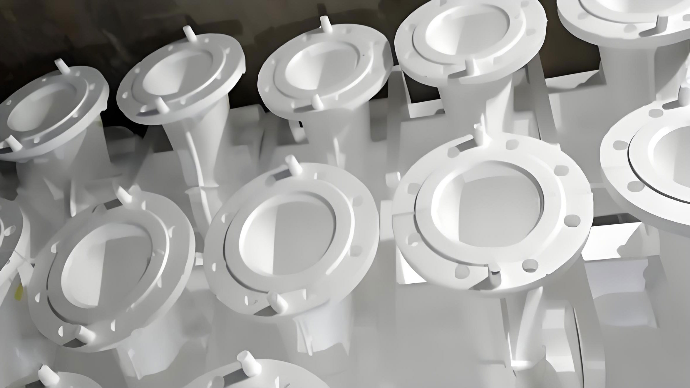
The impeller’s complex geometry usually necessitates a split-pattern design. The pattern is divided into two halves (e.g., the front shroud and the vane/back shroud assembly) to facilitate molding and ensure vane profile accuracy. The tooling for producing these foam patterns is typically machined from aluminum (e.g., ZL104) for its good thermal conductivity and machinability. A multi-cavity mold (e.g., 4-6 impressions) is common for productivity.
2. The Science of Foam: Pre-expansion and Molding
The heart of the **lost foam casting** process is the expendable foam pattern. Its properties are critical. We start with virgin EPS beads with a specified particle size distribution. For thin-section castings like impeller vanes, a finer bead size (e.g., 0.3-0.5 mm) is essential to capture detail and achieve a smooth surface.
Pre-expansion: Raw beads are pre-expanded using steam to achieve a low bulk density (typically 20-25 g/L for iron casting). The process can be modeled by considering the pressure of pentane blowing agent inside the bead. The ideal gas law gives a simplified relation:
$$ P_{pentane} V_{bead} = nRT $$
During steam heating, the polystyrene softens, the pentane pressure increases, and the bead expands. The final density $\rho_f$ is controlled by the temperature-time profile:
$$ \rho_f \propto \frac{1}{T \cdot t_{exp}} $$
where $T$ is the steam temperature and $t_{exp}$ is the exposure time. Precise control here is vital for consistent pattern quality.
Aging: Pre-expanded beads are then stabilized (“aged”) for several hours at ambient conditions. This allows air to diffuse into the cells, equalizing internal and external pressure, which improves flowability during the final molding and prevents bead collapse.
Pattern Molding: Aged beads are blown into the aluminum mold cavity. Steam is injected again, causing the beads to expand further, fuse at their boundaries, and take the exact shape of the cavity. The cycle involves steam heating, a brief holding period, and then cooling via water channels. Key parameters include steam pressure (0.3-0.5 MPa), cycle time, and cooling efficiency. Under-molding leads to poor bead fusion and a friable pattern; over-molding causes bead shrinkage and surface defects.
| Process Stage | Key Parameter | Typical Value / Range | Objective |
|---|---|---|---|
| Pre-expansion | Bulk Density | 20-25 g/L | Achieve low density for easy gasification |
| Bead Size (Post-Exp) | 0.3-0.5 mm | Replicate fine features, smooth surface | |
| Pattern Molding | Steam Pressure | 0.35-0.55 MPa | Adequate fusion without degradation |
| Cooling Time | 60-90 seconds | Dimensional stability before demolding | |
| Aging / Drying | Time | >72 hours at 20-25°C | Stabilize pattern, remove residual moisture |
3. Pattern Assembly and Coating Application
The molded pattern halves must be assembled with precision. Using dedicated fixtures, the parts are joined using low-residue hot-melt adhesives. The goal is a seamless, strong joint with minimal adhesive bead that could create a surface imperfection on the final casting.
The assembled foam pattern cluster (multiple impellers attached to a gating system) is then coated with a refractory slurry. This coating is arguably the most critical element in the **lost foam casting** process. It serves multiple functions: it provides a barrier between the sand and the molten metal, reinforces the fragile foam pattern, allows the decomposition gases to escape, and must withstand thermal shock.
The slurry is typically a water-based suspension of refractories (e.g., silica flour, zircon, alumina), binders (colloidal silica, clay), and additives. Its properties are finely tuned:
- Permeability: Must be high enough to allow rapid gas evacuation but low enough to prevent metal penetration. Permeability $k$ can be approximated by the Kozeny-Carman equation for a packed bed:
$$ k \approx \frac{\phi^3}{K S_0^2 (1-\phi)^2} $$
where $\phi$ is coating porosity, $S_0$ is specific surface area of the refractory, and $K$ is a shape factor. - Thickness: Usually 0.2-0.8 mm per coat, applied by dipping or spraying. Multiple coats are common.
- Strength & Drying: The coated patterns are dried thoroughly in controlled ovens (40-60°C) to develop green strength and remove water. Incomplete drying leads to steam explosions during pouring.
4. Sand Filling, Compaction, and the Vacuum’s Role
The dried, coated pattern clusters are placed in a vented flask. Unbonded, dry sand—often rounded silica sand or more expensive but superior ceramic sands like “Zircon” or “Chromite”—is then filled around them. The sand is compacted using multi-axis vibration to achieve a uniform and high bulk density without distorting the fragile pattern. The degree of compaction $\rho_{sand}$ directly influences mold rigidity.
The flask is then sealed with a plastic film and connected to a vacuum pump. Applying a vacuum (typically 0.04-0.07 MPa) does two things: it rigidizes the loose sand by creating a pressure differential (the “mass effect”), and it establishes a pressure gradient to evacuate foam pyrolysis gases. The pressure difference $\Delta P$ supporting the mold wall is given by:
$$ \Delta P = P_{atm} – P_{vac} $$
This negative pressure must be maintained throughout pouring and initial solidification.
| Defect | Likely Cause | Corrective Action |
|---|---|---|
| Carbon Inclusions (Folds, Lustrous Carbon) | Slow pouring, low pouring temp, poor foam degradation, low vacuum | Increase pour temp & speed; optimize coating permeability; ensure adequate vacuum |
| Incomplete Filling (Misruns) | Metal front freezing, excessive gas pressure, low vacuum | Increase superheat; check coating dryness & permeability; increase vacuum level |
| Surface Roughness (Peeling, Rat Tails) | Coating failure, sand collapse, high gas pressure | Improve coating adhesion/drying; ensure proper sand compaction; adjust vacuum |
| Dimensional Variation | Inconsistent foam density, pattern distortion during coating/sand fill | Standardize pre-expansion & molding; use gentler coating application; optimize vibration parameters |
5. Metallurgy, Pouring, and Solidification
For gray iron impellers, the melt chemistry is tightly controlled. A hypereutectic composition (e.g., 3.2-3.6% C, 1.8-2.4% Si) promotes fluidity and graphite formation. Inoculation is critical to ensure a fine, Type A graphite distribution and prevent chilling in thin sections.
Pouring is a critical phase in **lost foam casting**. The metal must fill the mold before the decomposing foam collapses the sand cavity. The filling velocity $v$ must overcome the gas generation rate $\dot{G}$ from the foam. A simplified energy balance at the metal-foam interface considers the heat required to pyrolyze the foam:
$$ \rho_m C_p (T_{pour} – T_{decomp}) \cdot A \cdot v = \rho_f \Delta H_{pyro} \cdot A \cdot v + \dot{Q}_{loss} $$
where $\rho_m, \rho_f$ are metal and foam densities, $C_p$ is metal heat capacity, $T_{decomp}$ is foam decomposition temperature (~500°C for EPS), $\Delta H_{pyro}$ is heat of pyrolysis, $A$ is interfacial area, and $\dot{Q}_{loss}$ is heat loss to coating/sand. This dictates that a higher pouring temperature and speed are generally needed compared to sand casting. For iron, a pouring temperature of 1380-1420°C is typical.
The vacuum is maintained during and after the pour until the casting has solidified enough to withstand the sand pressure. The solidification sequence, influenced by the impeller’s geometry and the chilling effect of the sand, must be managed to avoid shrinkage porosity, often through directional solidification towards the feeder in the gating system.
6. Shakeout, Cleaning, and Finishing
After sufficient cooling, the vacuum is released. The flask is inverted, and the loose sand flows away, revealing the casting cluster—a stark contrast to the labor-intensive knockout of traditional sand molds. The castings are separated from the gating system by sawing or grinding. The excellent surface finish from the **lost foam casting** process means minimal shot blasting or grinding is required. The impellers typically proceed directly to machining of critical interfaces (e.g., bore and hub faces) with minimal stock allowance.
The Tangible Benefits: Quantifying the Advantage
The adoption of **lost foam casting** for components like pump impellers delivers measurable benefits across the manufacturing value chain:
- Product Performance: Hydraulic efficiency improvements of 5-10% are achievable due to smoother, more accurate flow passages, consistent vane profiles, and reduced wall thickness variation.
- Manufacturing Efficiency: Process yield increases (>75%), machining allowance decreases (by 50-70%), and cleaning labor is drastically reduced. The sand system is simplified and environmentally cleaner.
- Quality & Consistency: Automation potential reduces human error. Dimensional repeatability improves, leading to better pump assembly and balance.
The successful implementation in leading pump manufacturing companies stands as a testament to its viability. These pioneers have demonstrated that **lost foam casting** is not merely an alternative but a superior pathway for producing high-integrity, complex castings.
Future Perspectives and Concluding Remarks
The evolution of **lost foam casting** continues. Research focuses on developing alternative pattern materials (e.g., polymethylmethacrylate – PMMA) that produce less carbon residue, advanced coating formulations with nano-additives for enhanced performance, and integrated simulation tools that couple computational fluid dynamics (CFD) for filling with finite element analysis (FEA) for stress and distortion during cooling. The drive towards full automation of the pattern handling, coating, and sand filling operations will further enhance productivity and consistency.
In conclusion, **lost foam casting** represents a paradigm shift in the production of critical components like submersible pump impellers. By mastering the interplay of foam science, refractory coating technology, granular mechanics of sand, vacuum physics, and metallurgy, this process delivers exceptional geometric fidelity, material properties, and economic efficiency. As the foundry industry marches towards greater sustainability and digital integration, **lost foam casting** is poised to solidify its role as a cornerstone technology for precision casting, transforming intricate designs into reliable, high-performance metal parts.