
In the field of mechanical engineering and petroleum drilling, the turntable serves as a critical component for driving drilling tools, enabling operations such as reverse rotation, casing milling, and grinding. The quality of this casting part directly impacts the performance and reliability of the entire system. Therefore, optimizing the casting process is essential to achieve a defect-free and high-integrity casting part. This study focuses on the upper turntable body, a medium-sized disc-shaped casting part made of HT300 gray iron with a net weight of 502 kg. Using ProCAST software, I conducted a comprehensive numerical simulation to analyze and optimize the solidification process, aiming to eliminate defects like shrinkage porosity and shrinkage cavity. The research involved designing two initial casting schemes, simulating filling velocity fields, predicting defects, and iteratively optimizing through riser and chill placements. The results demonstrate that a bottom-pouring vertical gating system, combined with strategic risers and chills, can transform the temperature field from mushy to sequential solidification, significantly improving the quality of the casting part.
The upper turntable casting part has complex structural features, including multiple holes and varying wall thicknesses. Its external dimensions are φ1281 mm × 101 mm, with a maximum wall thickness of 101 mm around the central hole and a minimum of 15.5 mm at the outer contour. For such a casting part, sand casting with furan resin sand was selected due to its cost-effectiveness, simplicity, and suitability for complex shapes. Key process parameters were determined based on industry standards: dimensional tolerance of CT11 per GB/T 6414-1999, weight tolerance of 8% per GB/T 11351-1989, machining allowance grade G, and a free contraction rate of 0.9% for gray iron. To streamline the process, holes smaller than 40 mm were excluded from the casting design, as they are impractical to cast directly. The following table summarizes the primary specifications of the casting part:
| Parameter | Value | Unit |
|---|---|---|
| Material | HT300 Gray Iron | – |
| Net Weight | 502 | kg |
| Gross Weight (Estimated) | Approx. 600 | kg |
| Dimensions (Diameter × Height) | φ1281 × 101 | mm |
| Maximum Wall Thickness | 101 | mm |
| Minimum Wall Thickness | 15.5 | mm |
| Casting Method | Sand Casting with Furan Resin Sand | – |
| Dimensional Tolerance | CT11 (9 mm for 1000–1600 mm) | mm |
| Weight Tolerance | 8% | – |
| Machining Allowance | Grade G | – |
| Contraction Rate | 0.9% | – |
In designing the casting process for this casting part, the selection of pouring position and parting surface is crucial. Two initial schemes were considered: a wraparound injection flat pouring and a bottom injection vertical pouring. After evaluation, the bottom-pouring vertical scheme was chosen because it allows for easier molding with two-part flasks, reduces misalignment risks, and ensures stable filling with minimal turbulence. The parting surface was set at the maximum diameter of the casting part to facilitate pattern withdrawal. The gating system was designed to achieve a controlled filling time. According to empirical formulas for casting parts under 1000 kg, the pouring time \( t \) is calculated as:
$$t = S_1 \sqrt[3]{\delta G_L}$$
where \( S_1 = 1.7 \), \( \delta \) is the average wall thickness in mm, and \( G_L \) is the weight of poured metal in kg. For this casting part, with \( \delta \approx 20 \) mm and \( G_L \approx 600 \) kg, the theoretical pouring time is 41 s. The choke cross-sectional area \( A_{\text{min}} \), which dictates the flow rate, was determined using:
$$A_{\text{min}} = \frac{G}{0.31 \times 10^5 \mu t \sqrt{H_p}}$$
with \( H_p = H_0 – 0.125h_c \). Here, \( G = 600 \) kg, \( \mu = 0.48 \), \( t = 41 \) s, \( H_0 = 0.377 \) m, and \( h_c = 0.101 \) m, yielding \( A_{\text{min}} = 17.26 \, \text{cm}^2 \). The gating ratio was set as \( \Sigma A_{\text{sprue}} : \Sigma A_{\text{runner}} : \Sigma A_{\text{ingate}} = 1.11 : 1.06 : 1 \), resulting in a sprue cross-section of 19.16 cm², a trapezoidal runner of 18.30 cm², and three ingates with a total area of 17.26 cm². A basin-type pouring cup was incorporated to reduce turbulence and slag inclusion. The table below outlines the gating system design details:
| Component | Cross-Sectional Area (cm²) | Dimensions | Remarks |
|---|---|---|---|
| Sprue | 19.16 | Diameter: 25–40 mm, Length: 800 mm | Tapered design |
| Runner | 18.30 | Trapezoidal shape | Single runner |
| Ingates (3) | 17.26 total (5.75 each) | Circular cross-section | Evenly distributed |
| Pouring Cup | Basin-type | Designed for 600 kg pouring | Reduces turbulence |
For simulation, the 3D model of the casting part was created and meshed into 804,990 elements in ProCAST. The material was set as HT300 gray iron, with a pouring temperature of 1360°C and boundary conditions defined: metal-sand heat transfer coefficient \( h = 500 \, \text{W/(m}^2 \cdot \text{K)} \), sand-chill \( h = 500 \, \text{W/(m}^2 \cdot \text{K)} \), and metal-chill \( h = 2000 \, \text{W/(m}^2 \cdot \text{K)} \). The filling velocity field simulation revealed that the casting part could be filled in 40.39 s, closely matching the theoretical 41 s. The liquid metal advanced in a layered manner without significant turbulence, as shown by velocity contours at different times: at 1.90 s, metal entered the cavity through ingates; at 11.48 s, one-third filled; at 32.76 s, two-thirds filled; and at 40.39 s, complete filling. This indicated a stable filling process suitable for the casting part. However, defect prediction without risers or chills showed severe shrinkage porosity and shrinkage cavity around thick sections and hole clusters, typical of gray iron’s mushy solidification. The porosity percentage was estimated using the Niyama criterion, approximated as:
$$P \propto \frac{G}{\sqrt{\dot{T}}}$$
where \( G \) is the temperature gradient and \( \dot{T} \) is the cooling rate. Low values indicated defect-prone zones in the casting part.
The first optimization involved adding two open-top risers at the upper notches of the casting part to facilitate feeding and排气. The risers were designed with a necked shape to delay solidification, using modulus method calculations. Additionally, five gray iron chills (HT300, 50 mm thick, 120 mm long, 60 mm wide) were placed around thick sections to enhance cooling. The chill weight \( G_{ch} \) and thickness \( D \) were derived from:
$$D = \frac{G_{ch}}{7.3S}$$
with \( S \) as the chill area. Simulation after this optimization showed reduced defects, but some shrinkage persisted near ingates and thin walls, likely due to premature riser neck solidification or insufficient chilling. The second optimization adjusted chill placement and size: three more chills (150 mm × 60 mm × 50 mm) were added around small holes on the outer contour, and five larger chills (200 mm × 120 mm × 50 mm) were positioned at central thick areas. This modification increased the cooling rate, altering the temperature gradient to promote sequential solidification. The final simulation demonstrated complete elimination of shrinkage defects, with filling time reduced to 29.30 s. The temperature field transitioned from mushy to sequential, ensuring directional solidification from thin to thick sections, aided by riser补缩. The effectiveness of optimizations is summarized below:
| Optimization Step | Changes | Filling Time (s) | Defect Status | Solidification Mode |
|---|---|---|---|---|
| Initial Design | No risers or chills | 40.39 | Severe shrinkage in thick zones | Mushy |
| First Optimization | 2 risers + 5 chills | ~40 | Reduced but residual defects | Partial sequential |
| Second Optimization | Added 8 more chills, adjusted sizes | 29.30 | No defects detected | Fully sequential |
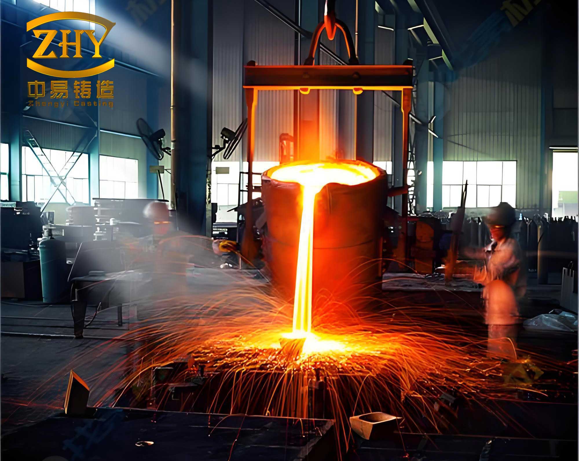
The success of this optimization highlights the importance of numerical simulation in refining casting processes for complex casting parts. By integrating ProCAST analysis, I could visualize flow patterns and defect formation, enabling data-driven adjustments. The use of chills and risers effectively managed heat dissipation, a critical factor for gray iron casting parts prone to shrinkage. The final design ensures that the casting part solidifies directionally, with risers providing adequate molten metal to compensate for contraction. This approach not only improves quality but also reduces production costs by minimizing trial runs. The image below illustrates a typical steel casting part, reminiscent of the turntable’s structural complexity, underscoring the relevance of such optimizations in industrial applications.
In conclusion, this study demonstrates a systematic method for optimizing the solidification process of an upper turntable casting part using ProCAST. The initial bottom-pouring vertical gating system provided stable filling, but defect analysis revealed the need for risers and chills. Through iterative simulations, the optimal configuration included two necked risers and thirteen strategically placed chills, which transformed the solidification behavior and eliminated defects. The casting part achieved a shorter filling time of 29.30 s and a sequential temperature field, ensuring high integrity. These findings underscore the value of numerical simulation in casting design, particularly for medium-sized casting parts with intricate geometries. Future work could explore other materials or cooling techniques to further enhance the performance of such casting parts. Overall, this research contributes to advancing casting technology, offering a replicable framework for optimizing similar casting parts in various industries.