
The demand for high-performance, lightweight, and reliable components in modern transportation sectors like rail transit has driven the advancement of large-scale aluminum alloy casting technology. Among these critical components, the gearbox housing stands out as a fundamental casting part that ensures the integrity and efficiency of the entire transmission system. This article details the comprehensive development process for a large aluminum alloy gearbox casting part intended for high-speed train applications, focusing on the intricate interplay between structural design, process engineering, simulation, and quality control. The successful production of such a complex casting part necessitates a methodical approach to overcome challenges related to uneven wall thickness, dispersed thermal masses, and stringent mechanical property requirements.
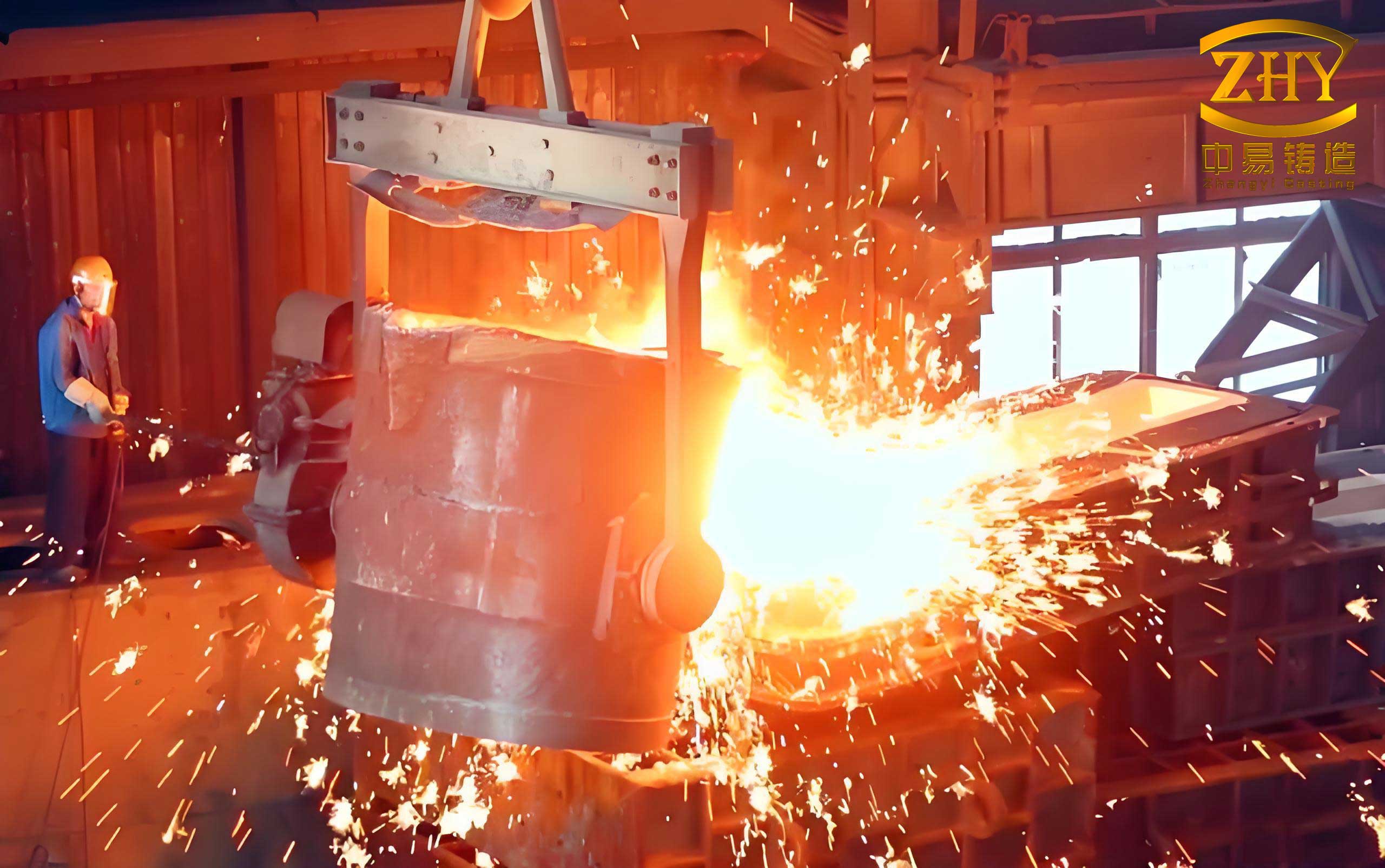
The target gearbox casting part is characterized by its substantial dimensions and intricate geometry. Its structural complexity presents a classic foundry challenge, featuring a combination of thin walls, thick sections, and an extensive network of internal and external ribs and channels. The primary specifications and requirements for this critical casting part are summarized in the table below:
| Parameter | Specification |
|---|---|
| Overall Dimensions | 977 mm × 660 mm × 402 mm |
| Nominal Weight | 265 kg |
| Wall Thickness Range | 12 mm (min) to 116 mm (max) |
| Alloy Designation | AlSi7Mg0.3 (A356 equivalent) |
| NDT Requirement (Key Areas) | ASTM E155 Level 2 |
| Tensile Strength (Rm) | ≥ 270 MPa |
| Yield Strength (Rp0.2) | ≥ 220 MPa |
| Elongation (A) | ≥ 3.5 % |
| Hardness (HBW) | ≥ 75 |
The significant disparity in section thickness within a single casting part leads to the formation of numerous isolated thermal centers, or hot spots. These areas are prone to shrinkage porosity and cavities if the solidification sequence is not meticulously controlled. Furthermore, the mechanical property targets, especially for yield strength and elongation, exceed conventional standards for this alloy family, demanding exceptional melt quality and solidification control.
Foundry Process Selection and Initial Design Philosophy
To manufacture this demanding gearbox casting part, a combination of furan resin sand molds and low-pressure casting was selected. This approach offers distinct advantages for producing large, complex, and high-integrity components. The low-pressure process involves filling the mold cavity with molten metal from a sealed furnace by applying a controlled gas pressure (typically in the range of 0.3 to 0.8 bar). The metal rises smoothly through a central stalk (or multiple stalks) into the mold. The fundamental principle governing the filling and feeding can be described by a simplified pressure balance equation:
$$ P_{applied} = \rho g h + \Delta P_{flow} $$
Where \( P_{applied} \) is the pressure exerted on the melt surface in the furnace, \( \rho \) is the melt density, \( g \) is gravitational acceleration, \( h \) is the height of the metal column from the furnace to the top of the mold cavity, and \( \Delta P_{flow} \) represents pressure losses due to friction in the feeding system. The primary advantage for a casting part of this size is the inherent ability to promote directional solidification. The regions farthest from the ingate (point of metal entry) solidify first, while the ingate itself, kept hot by continuous metal flow from the furnace, solidifies last, acting as an effective feeding riser. This significantly enhances the soundness and density of the final casting part.
The initial gating system was designed as an open type to ensure non-turbulent filling: the total cross-sectional area of the ingates (\( \Sigma F_{ingate} \)) was designed to be larger than that of the runners (\( \Sigma F_{runner} \)), which in turn was larger than the stalk area (\( \Sigma F_{stalk} \)). However, to ensure adequate feeding pressure during solidification, the individual stalk cross-section (\( F_{stalk} \)) was designed to be the largest in its local section. Given the size and geometry of the casting part, a twin-stalk system was employed to ensure even filling and adequate feeding capacity to multiple heavy sections. Chills were strategically placed on the mold at major thermal centers to accelerate local cooling and promote a favorable temperature gradient. Additionally, overflow vents were placed at the last points to fill, helping to evacuate cold or oxide-laden metal and improve temperature distribution.
Leveraging CAE Simulation for Process Optimization
Given the complexity and cost associated with prototyping such a large casting part, numerical simulation using MAGMAsoft was integral to the development cycle. The primary objectives were to visualize and optimize the filling pattern to avoid turbulence and to predict the solidification sequence to eliminate shrinkage defects.
The initial simulation revealed potential issues with the filling pattern and final temperature distribution. Based on these insights, the gating system and chill layout were iteratively optimized. The final simulated fill sequence showed a remarkably flat, rising metal front with minimal velocity, confirming a laminar fill. The temperature field at the end of filling showed that all areas were above the liquidus temperature (613°C for AlSi7Mg0.3), with the internal and lower sections being hotter—a prerequisite for sound feeding.
The most critical analysis was the solidification simulation coupled with a shrinkage prediction criterion (e.g., Niyama criterion). The criterion often takes a form related to thermal gradients (G) and cooling rates (R):
$$ \frac{G}{\sqrt{\dot{T}}} \geq C $$
Where \( G \) is the temperature gradient, \( \dot{T} \) is the cooling rate, and \( C \) is a critical value specific to the alloy. Areas where this value falls below the threshold are predicted to be prone to microporosity. The optimized process, incorporating the twin stalks, chills, and overflows, demonstrated a largely directional solidification pattern starting from the outer walls and thin sections towards the ingates. The shrinkage prediction model indicated that while some minor, acceptable microporosity might exist in non-critical, isolated heavy sections, all critical, highly-stressed areas of the gearbox casting part were predicted to be sound. This virtual validation provided the confidence to proceed to tooling and physical trials.
Controlled Melting, Treatment, and Pouring Parameters
The quality of the final casting part is fundamentally rooted in melt quality. The AlSi7Mg0.3 alloy was melted in an electric resistance furnace. After reaching a temperature of 720-750°C, the melt was subjected to a rigorous rotary degassing treatment for 30 minutes using an inert gas (typically Argon or Nitrogen) to reduce hydrogen content. Simultaneously, a strontium-based modifier (Al-10Sr) was added at 0.2-0.4 wt.% to refine the eutectic silicon morphology, which is crucial for achieving the required ductility. Melt quality was quantitatively assessed using a reduced pressure test (RPT), where a sample solidified under vacuum must achieve a density greater than 2.64 g/cm³ to be deemed acceptable for casting.
The low-pressure casting cycle is defined by a precise pressure-time curve. For this gearbox casting part, the cycle was broken down into several stages with carefully tuned parameters:
| Stage | Parameter Control | Objective |
|---|---|---|
| 1. Pressurization / Rise | Ramp pressure to ~0.15 bar at 800 Pa/s. | Lift metal smoothly to the bottom of the mold cavity. |
| 2. Filling | Increase pressure to ~0.5-0.6 bar to fill cavity. Total fill time ~90-120s. | Maintain a quiet, laminar front velocity <0.5 m/s. |
| 3. Intensification (Pressure Solidification) | Rapidly increase pressure to ~0.8 bar and hold for 300-400s. | Feed shrinkage during solidification, increasing casting part density. |
| 4. Pressure Release | Vent pressure to atmosphere. | Allow remnant liquid in stalk to drain back to furnace. |
The pouring temperature was adjusted based on ambient conditions: 700-720°C for shop temperatures below 10°C, and 690-710°C for temperatures between 10-40°C. This compensation helps achieve consistent mold filling characteristics and final microstructure in the large casting part.
Defect Analysis and Corrective Actions in Series Production
Initial production runs successfully yielded conforming casting parts, but two specific, recurring defects were identified, requiring further process refinement.
1. Shrinkage Porosity near Ingates: Isolated shrinkage cavities and porosity were detected in heavy sections adjacent to the ingates on the parting plane. Analysis pointed to two contributing factors. First, the local sand mold compactness in these high-heat-load areas was insufficient, leading to mold wall movement and localized slow cooling. Second, the initial ingate cross-sectional area, while adequate for filling, provided marginal feeding capacity for the substantial thermal mass it was attached to.
Corrective Actions: First, the sand in the critical ingate areas on the mold was replaced with shell sand (coated sand). Shell sand molds exhibit higher strength, density, and thermal stability, resisting deformation and improving heat extraction, thereby reducing the local solidification time. Second, the thickness of the ingates was increased from 25mm to 35mm. This enhanced the feeding “reservoir” capacity, effectively shifting the last point of solidification deeper into the gating system and away from the casting part itself. The effectiveness of these changes was confirmed by a revised solidification simulation and subsequent inspection of casting parts.
2. Gas Porosity at High-Point Venting Features: Pin-hole porosity was consistently found at the top of certain upward-protruding vent bosses. These areas were the last to fill and acted as natural gas collection points. The long flow distance resulted in some heat loss, increasing melt viscosity and trapping gas bubbles that could not escape before solidification.
Corrective Actions: Additional side-feeding channels (small runners) were introduced near the base of these vent features. This provided a direct, hotter metal path to these areas, raising the local temperature and improving fluidity to allow gas to escape. Furthermore, the size and number of overflow vents at the mold’s highest points were increased to enhance the overall venting capacity of the system, reducing back-pressure on escaping gases.
The summary of these defect-resolution iterations is presented below:
| Defect Type | Root Cause Hypothesis | Corrective Action | Outcome |
|---|---|---|---|
| Shrinkage near Ingates | 1. Inadequate local mold strength/heat transfer. 2. Marginal feeding capacity of ingate. |
1. Replace local sand with shell sand. 2. Increase ingate thickness from 25mm to 35mm. |
Elimination of major shrinkage defects in critical areas of the casting part. |
| Gas Porosity at High Points | Gas entrapment due to long flow distance and localized cooling. | 1. Add local side-feeding channels. 2. Increase overflow vent capacity. |
Significant reduction and eventual elimination of gas-related defects. |
Final Product Validation and Conformance
The implemented and optimized process yielded a consistently high-quality gearbox casting part. Comprehensive validation was performed on production samples.
Mechanical Properties: Test coupons machined from critical, high-stress locations (such as lifting lugs) on the casting part itself (本体取样) were tested. The results significantly exceeded the minimum requirements, demonstrating the effectiveness of the controlled low-pressure solidification and melt treatment.
| Property | Requirement | Casting Part Sample 1 | Casting Part Sample 2 |
|---|---|---|---|
| Tensile Strength (Rm) | ≥ 270 MPa | 295 MPa | 311 MPa |
| Yield Strength (Rp0.2) | ≥ 220 MPa | 246 MPa | 253 MPa |
| Elongation (A) | ≥ 3.5 % | 5.0 % | 8.0 % |
| Hardness (HBW) | ≥ 75 | 99 | 103 |
Non-Destructive Testing (NDT): Radiographic examination (X-ray and DR imaging) of all key areas, including mounting flanges and the parting plane, confirmed the internal soundness of the casting part. The quality level consistently met the stringent ASTM E155 Level 2 standard, with no unacceptable shrinkage or gas porosity detected.
Leak Test: Every finished gearbox casting part underwent a hydrostatic pressure test at 0.1-0.15 MPa. No leaks were observed at any seams or walls, verifying the structural integrity and high density achieved through the optimized low-pressure process.
Conclusions and Broader Implications
The successful development of this large, complex aluminum alloy gearbox casting part underscores the necessity of a holistic, science-based approach to modern foundry engineering. The integration of several key methodologies was crucial:
- Process Selection: The low-pressure sand casting process was fundamentally suited for this application, providing the controlled filling and superior feeding capability required for a large, structurally demanding casting part.
- Simulation-Driven Design: CAE simulation was not merely a verification tool but an active design partner. It enabled the virtual prototyping and optimization of the gating system, chilling strategy, and overflow placement, drastically reducing development time, cost, and material waste.
- Rigorous Process Control: From melt treatment with degassing and modification to the precise execution of the low-pressure casting curve, each parameter was defined and controlled to ensure consistent, high-quality outcomes for every casting part.
- Iterative Problem-Solving: The systematic analysis of production defects and the implementation of targeted corrective actions—such as material substitution (shell sand) and geometric modifications (enlarged ingates)—demonstrate the continuous improvement cycle essential for robust manufacturing.
The final product is a testament to these efforts: a lightweight, high-strength, and leak-proof aluminum alloy gearbox casting part that fully meets the rigorous demands of high-speed rail service. The methodologies and lessons learned, particularly in managing solidification in a highly heterogeneous casting part, provide a valuable blueprint for the development of other large-scale, safety-critical aluminum castings across the transportation and heavy machinery industries. The consistent production of such a casting part validates the low-pressure sand casting process as a premier method for achieving superior metallurgical quality and geometric integrity in complex, thin-to-thick walled components.