
1. Sand mold casting process scheme of nodular cast iron
Nodular cast iron sand castings are produced in single piece and small batch. The material of nodular cast iron sand castings is QT500-7. According to en 12890, the quality level is H2 and the accuracy level is DIN iso8062-ct12; The minimum surface roughness shall be Ra12 5. The large hole surface and flange mating surface shall reach RA3 after cutting 2; Nodular cast iron sand castings have high quality requirements and can not have defects such as sand inclusion, shrinkage cavity and porosity. In order to meet the technical requirements of nodular iron sand castings, the quality of nodular iron sand castings should be guaranteed as much as possible, and the simple process and production cost should be taken as the second consideration. Through the comparison of various schemes, the pouring position which can best ensure the quality of nodular cast iron sand mold castings is selected; Then find out the simplest and most economical production method on the premise of ensuring the quality of nodular cast iron sand mold castings, so as to achieve good quality, simple production process and low production cost.
Based on the comprehensive analysis of the structure and processability of nodular cast iron sand mold castings, it is determined to adopt self hardening resin sand molding. At the same time, considering the large size of nodular cast iron sand mold castings, it is necessary to use sand box to maintain and fix the sand mold.
2. Selection of pouring position for nodular cast iron sand mold casting
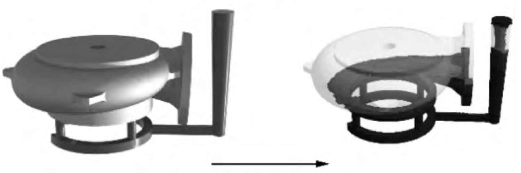
Through the analysis of the structure of nodular cast iron sand mold castings, according to the selection principle of parting surface, two pouring positions are generally selected as shown in Figure 1. At the pouring position shown in Fig. 1 (a), the large disc of the spiral case of nodular cast iron sand casting is at the bottom, the defects such as air hole and slag inclusion float upward, which is easy to lead to large hole surface defects, and the required cutting accuracy grade RA3 in the large circular hole at the upper part 2. The precision requirements are high. After defects occur in the upper part, the compactness of nodular cast iron sand castings cannot be guaranteed, and the fit is not tight, which can not meet the requirements of parts. At the same time, the core is not easy to fix, so the core support needs to be used to increase the modeling difficulty.
The pouring position shown in Figure 1 (b) adopts the pouring method of placing the large plane of nodular cast iron sand mold casting on the top and the large opening on the bottom. The important large hole surface is at the lower part, which can better ensure the quality of nodular cast iron sand mold casting. This pouring method is also conducive to the fixation of the core, and there is no need to use the core support. After comparative analysis, the pouring position in Figure 1 (b) is adopted.
3. Selection of parting surface of nodular cast iron sand mold
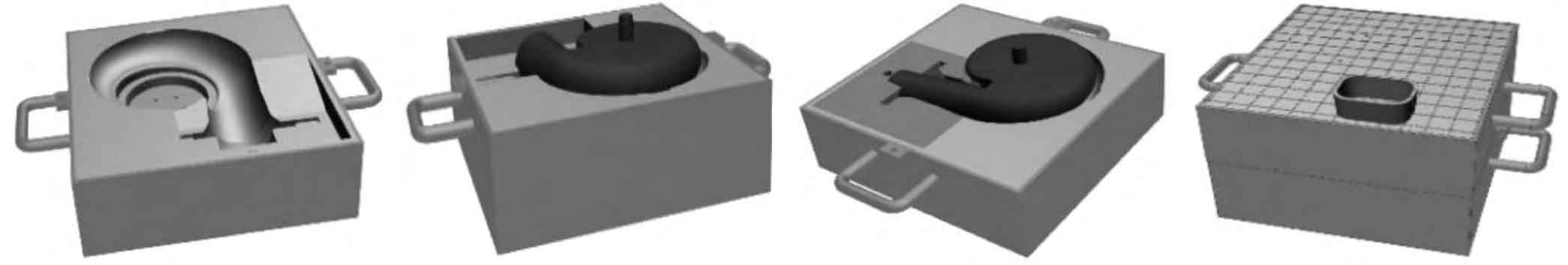
The parting surface is selected at the maximum section of nodular cast iron sand mold casting (as shown in Figure 2) for mold lifting; the parting surface is flat, and small inserts are set on the inclined flange to simplify modeling and template manufacturing, which is conducive to ensuring the dimensional accuracy of nodular cast iron sand mold casting, as well as lower core and box closing.
4. Design of gating system for nodular cast iron sand mold casting
According to the design principle of the gating system, the following two gating system schemes are often set for the nodular cast iron sand casting of this kind of spiral case: ① the runner is set around the annular spiral case, and the four inner sprues are connected with the outer wall of the spiral case; ② The bottom pouring method is adopted, and the inner sprue is connected with the bottom end of the large hole. The runner of the gating system (Fig. 3 (a)) is too long, and the metal liquid is easy to produce sand flushing and entrainment during filling, and the simulation results show that the filling stability is not very good; the gating system (Fig. 3 (b)) needs to adopt three compartment modeling, and the runner is also long, which makes the modeling annoying.
After the above comparison, it is decided to adopt the gating system as shown in Figure 4: the liquid metal first enters the arc bottom of the flange from both ends of the outer edge of the flange, and then enters the similar spiral cavity for uniform filling from bottom to top. The liquid metal filling is fast and stable, the runner is the shortest, and the liquid metal is not easy to be oxidized; In addition, because the top wall thickness of the ductile iron sand casting is too large and the wall thickness of the inclined pipe at the flange end is too thin, the wall thickness of the ductile iron sand casting varies greatly. The inner sprue is set near the flange with the thinnest wall thickness of the ductile iron sand casting, which is conducive to reducing the temperature difference between cooling and solidification of the ductile iron sand casting and ensuring the uniformity of graphitization structure of all parts of the ductile iron sand casting.
For this nodular iron casting, if the feeding riser is designed at the top of the large plane, it is found through simulation that if the riser is designed to be small, the riser will solidify before the nodular iron sand casting, which can not achieve the feeding effect. If the riser is used for feeding, the riser needs to be designed very large. However, for the large plane at the top, if the riser is designed too large, it will bring inconvenience to the later processing, and the utilization rate of materials is not high. Because the CE value of nodular cast iron is high and the graphitization expansion is large, the graphitization expansion of nodular cast iron can be fully used to achieve self feeding. Because the casting modulus of this casting is 3.1 cm, and the inner sprue is designed to be thin, the design filling time is about 36 s, and the filling is fast, so it is suitable to use no riser pouring.
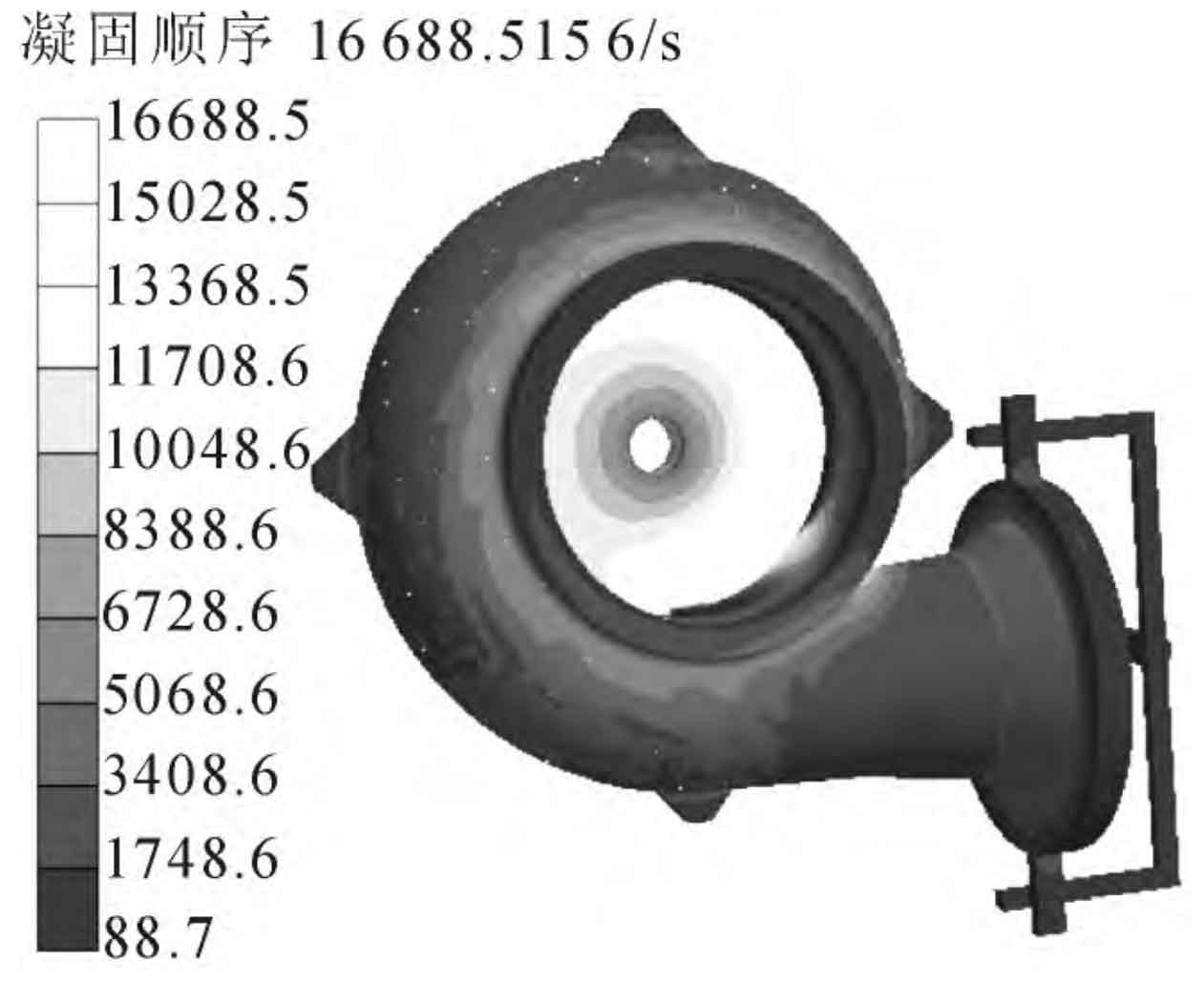
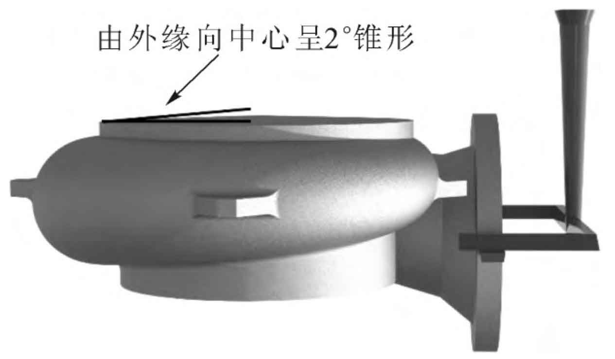
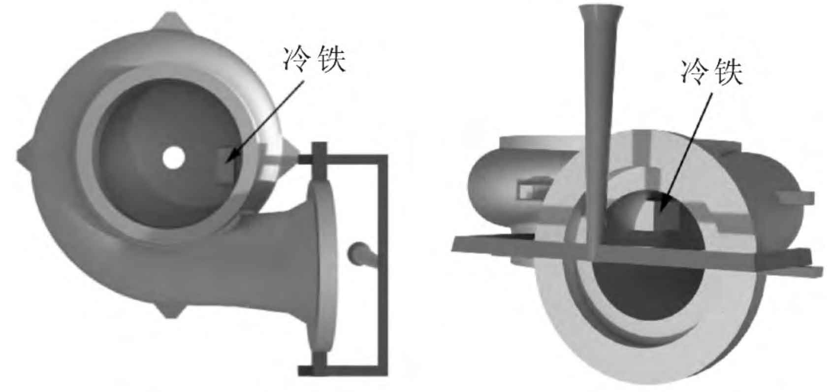
Combined with the simulation results of AnyCasting software, Use sand separating cold iron at hot joints and thick parts (as shown in Fig. 5 and Fig. 6), to reduce the temperature difference between solidification and crystallization of nodular cast iron sand castings; and pour at a relatively low temperature of 1280 ℃ ~ 1290 ℃, so that the molten iron fills the mold cavity. At the initial stage, it is fed by the inner gate, and at the later stage, the outer layer of nodular cast iron sand castings is crusted due to the condensation and sealing of the inner gate, and its internal crystallization shrinkage will expand due to graphitization And offset, so as to obtain non shrinkage ductile iron sand castings. In addition, the top of the large disc is designed to be 2 ℃ conical from the outer edge to the center (as shown in Figure 4), and 15 mm machining allowance is added to make as many pores and sand inclusion float into the cone as possible, and several uniform small air outlets are set on the top of the upper sand mold to ensure the quality of the upper surface of the large disc.
For the design of the sprue, because the nodular cast iron sand casting weighs nearly two tons, the pouring time is long, and the impact force caused by the drop is large. The pouring system made of self hardening resin sand is easy to cause the resin sand to collapse prematurely and lose strength under the long-time thermal action of high-temperature metal liquid, resulting in sand flushing defects. Therefore, the sprue of the nodular cast iron sand casting is made of ceramic pipe, At the same time, the problem that the sprue is not easy to be coated is solved, which plays a great role in improving the yield of nodular cast iron sand castings. In addition, sheet refractory bricks are placed under the sprue to prevent the scouring damage of falling liquid metal to the bottom of the sand mold.
5. Design of sand mold (core) of nodular cast iron sand mold
The inside of the nodular cast iron sand mold casting is a vortex cavity, and a whole large sand core is used to form a vortex structure. The small boss core on the top surface of the sand core can also fix the sand core and prevent the sand core from floating under the action of liquid metal; Add a small insert sand core to solve the problem that the flange inclined pipe hinders the forming of the mold lifting part; Then consider the handling, exhaust and weight reduction of the sand core, and hollow out the lower part of the large sand core. The upper and lower boxes are mechanically positioned and fastened to prevent the sand box from loosening during solidification and expansion of nodular cast iron sand castings.