
High manganese steel, characterized by its exceptional work-hardening capability and high impact toughness, remains a cornerstone material for manufacturing wear-resistant components, particularly liners for grinding mills and crushers in mining and cement industries. The performance and service life of these critical sand casting parts are profoundly influenced by their microstructure, which in turn is dictated by the thermal history and solidification behavior during the casting process. Therefore, meticulous control over casting technology is paramount. We will analyze the advancements in mainstream casting processes for these components and explore the increasingly vital role of numerical simulation in process design and optimization.
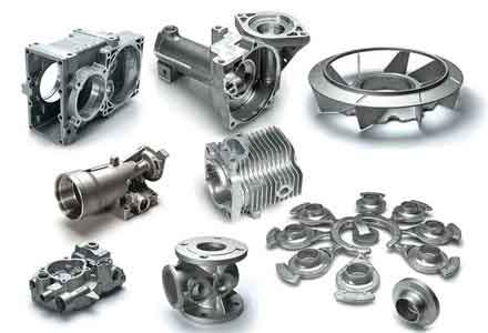
The quality of sand casting parts like mill liners is not inherent to the alloy alone but is forged in the foundry. Defects such as shrinkage porosity, gas holes, and coarse microstructure can severely compromise durability. Traditional casting development relied heavily on trial-and-error, which is costly and time-consuming for large, complex sand casting parts. The integration of computational modeling has revolutionized this approach, allowing for virtual prototyping and optimization. This review consolidates current knowledge on applying various casting methods and simulation techniques to produce superior high manganese steel liners.
1. Foundry Processes for High Manganese Steel Liners
The selection of a casting process involves a trade-off between cost, complexity, dimensional accuracy, and metallurgical quality. For large, wear-resistant sand casting parts, several methods have been developed and refined.
1.1 Sand Casting Process
Sand casting, due to its flexibility and low pattern cost, is widely used for producing large high-manganese steel liners. The key challenge is achieving directional solidification to feed shrinkage effectively in thick sections typical of these sand casting parts. Optimization focuses on the gating and feeding system design.
Traditional methods using multiple small risers often fail, leading to internal shrinkage. Advanced practice employs a reduced number of larger, more efficient risers, sometimes integrated with the gating system (gating-riser integration). The design rule often requires the riser’s modulus (volume/surface area) to be approximately 1.5 times that of the casting’s hot spot. External chills are strategically placed to accelerate cooling in isolated thick areas, promoting directional solidification towards the riser. However, internal chills are generally avoided in high manganese steel due to risks of poor fusion.
Pouring temperature is a critical parameter. While higher temperatures improve fluidity, they promote grain growth. An optimal window exists; studies suggest temperatures between 1,390°C and 1,410°C can yield a favorable balance, minimizing grain size and wear rate. The use of resin-bonded sand molds, often with a facing of magnesia olivine sand for its high refractoriness and chilling effect, combined with rare earth (RE) modification to refine carbides, represents a comprehensive quality enhancement strategy for these sand casting parts.
| Parameter/Optimization | Typical Range/Strategy | Impact on Sand Casting Parts |
|---|---|---|
| Riser Design | Modulus ≥ 1.5 x Hot Spot Modulus; Integrated gating-riser | Improves feeding, reduces shrinkage porosity. |
| Pouring Temperature | 1,390°C – 1,410°C (Optimal) | Controls grain size, minimizes wear rate. |
| Mold Material | Resin-bonded sand with magnesia olivine facing | Improves surface finish, provides chilling, reduces burn-on. |
| Melt Treatment | Rare Earth (RE) modification | Refines primary carbides, improves toughness. |
| Use of Chills | External chills in thick sections | Promotes directional solidification, refines microstructure. |
1.2 Metal Mold (Permanent Mold) Casting
To address limitations in surface finish and dimensional consistency of traditional sand casting parts, metal mold casting is employed. The permanent metal mold provides rapid and uniform heat extraction, leading to finer as-cast microstructure and often eliminating the need for subsequent water-quenching heat treatment for certain sections.
The core of this technology lies in the mold material’s thermal conductivity. Copper alloys, with high thermal diffusivity, are excellent but costly. A derivative process, sand-lined metal mold casting, applies a thin layer of sand onto the metal mold’s interior surface. This composite mold offers a controlled heat transfer rate—faster than pure sand but slower than pure metal—effectively suppressing the formation of coarse grain-boundary carbides in the as-cast state. This can yield a fine, homogeneous austenitic matrix directly after casting, significantly enhancing the properties of these specialized sand casting parts.
Process parameters are crucial. The interfacial heat transfer coefficient (IHTC) between the casting and the mold governs the cooling rate. It is highly dependent on the mold coating and pouring temperature. $$ IHTC = f(T_{\text{pour}}, \text{coating properties}, \text{interface pressure}) $$ A higher pouring temperature generally increases the peak IHTC, intensifying initial cooling. Coatings are essential to prevent soldering, control heat flow, and ease ejection. Research into advanced coating materials like hexagonal boron nitride (h-BN) composites aims to improve thermal shock resistance and environmental friendliness compared to traditional graphite-based coatings.
| Mold Type | Cooling Rate | Microstructure | Typical Post-Casting Treatment | Suitability for Complex Sand Casting Parts |
|---|---|---|---|---|
| Standard Metal Mold | Very High | Very Fine, Suppressed Carbides | Often unnecessary or simplified | Low (simple geometries) |
| Sand-Lined Metal Mold | Moderately High (Controlled) | Fine, Homogeneous Austenite | May be eliminated for specific grades | Medium |
| Traditional Sand Mold | Low | Coarser, Carbides at Boundaries | Water-Quenching required | High |
1.3 Lost Foam Casting (LFC)
Lost foam casting is advantageous for producing complex geometry sand casting parts with internal features, such as liners with integrated lifting bars or intricate contours. A foam pattern is embedded in unbonded sand, and molten metal replaces the vaporized pattern.
Process optimization centers on minimizing defects related to foam decomposition, such as fold defects and carbon uptake. Gating design is critical; bottom or side gating with multiple gates is preferred over top gating to ensure smooth, progressive filling and reduce turbulence. The use of low-density foam (STMMA copolymer) and precise coating control (typically zircon-based, 0.2-0.4 mm thick) are essential. Pouring temperature in LFC is usually higher than in conventional sand casting (e.g., ~1,480°C) to provide the energy needed for foam degradation, but must be balanced against increased grain growth.
An innovative approach is riser-less casting under controlled vacuum. By using a low pouring temperature to minimize liquid contraction and maintaining a specific vacuum level in the sand flask, simultaneous solidification can be achieved, eliminating shrinkage defects and the need for riser removal, thus improving yield and avoiding thermal stresses from cutting.
1.4 V-Process (Vacuum Molding) Casting
The V-Process uses a thin plastic film sealed over a pattern and backed with dry, unbonded sand held in place by vacuum. It produces sand casting parts with excellent surface finish, dimensional accuracy, and minimal veining defects due to the lack of binder.
Key parameters include vacuum level, film properties, and pouring temperature. The vacuum must be maintained throughout fill and solidification to preserve mold integrity. The process is sensitive to pouring temperature; too high a temperature can cause film burn-through and sand sintering, while too low can lead to misruns. An optimal range around 1,550°C is often targeted. The coating in V-Process must dry rapidly and withstand the initial thermal shock without the support of a bonded sand mold. Coatings with specific refractory aggregates like zircon or magnesia olivine powder, with controlled particle size distribution, are used to ensure good drying performance and resistance to metal penetration.
$$ \text{Drying Time} \propto \frac{\text{Coating Thickness}^2 \times \text{Binder Viscosity}}{\text{Permeability}} $$
Controlling these factors is essential for the efficient production of high-quality sand casting parts via the V-Process.
| Process | Key Mechanism | Major Advantages for Liners | Primary Challenges |
|---|---|---|---|
| Sand Casting | Bonded sand mold destruction after casting. | High flexibility, low tooling cost for large parts. | Shrinkage control, lower dimensional accuracy, poor sand reuse. |
| Metal Mold | Heat extraction via reusable metal mold. | Fine microstructure, good surface finish, high productivity. | High mold cost, limited geometry complexity, thermal fatigue of mold. |
| Lost Foam | Pattern vaporization by molten metal. | Excellent for complex geometries, no cores needed, minimal draft. | Pattern cost, potential for fold defects and carbon pickup. |
| V-Process | Dry sand held by vacuum on a plastic film. | Superior surface finish, dimensional accuracy, eco-friendly (no binders). | Sensitive to process parameters, film handling, requires robust vacuum system. |
2. Application of Numerical Simulation in Liner Development
Numerical simulation has become an indispensable tool for designing both the casting process and the liner geometry itself, moving beyond the traditional trial-and-error approach for sand casting parts.
2.1 Discrete Element Method (DEM)
DEM simulates the granular flow of grinding media (balls, ore) inside a mill. It is used to analyze the wear mechanisms and optimize the liner profile to enhance service life and grinding efficiency.
The method tracks individual particles, calculating contact forces and energies. By simulating the charge motion, engineers can quantify impact and abrasion wear on different liner sections. For example, the wear of lifting bars is identified as critical, proceeding from initial impact at the “toe” to severe abrasion in later stages. DEM enables parametric studies of design features:
- Lifter Height & Face Angle: Optimal height is often related to ball diameter (e.g., 60% of max ball diameter). The face angle (e.g., ~60°) can be tuned to maximize ore-breaking impact energy while minimizing direct liner-media impact energy, thus reducing wear.
- Lifter Profile: Modifications like adding secondary (“sub”) lifters can alter the charge trajectory, potentially improving grinding efficiency and wear distribution. However, complex profiles must be checked for localized stress concentrations.
DEM provides a particle-scale understanding of the in-service wear of sand casting parts, guiding geometry optimization before physical prototyping.
2.2 Finite Element Method (FEM)
FEM is primarily used to simulate the casting process (filling, solidification, cooling) and the heat treatment process. It helps predict and eliminate defects in sand casting parts.
For casting simulation, governing equations for fluid flow and heat transfer are solved:
Continuity: $$ \nabla \cdot \vec{v} = 0 $$
Momentum (Navier-Stokes): $$ \rho \left( \frac{\partial \vec{v}}{\partial t} + \vec{v} \cdot \nabla \vec{v} \right) = -\nabla p + \mu \nabla^2 \vec{v} + \rho \vec{g} $$
Energy: $$ \rho C_p \frac{\partial T}{\partial t} = \nabla \cdot (k \nabla T) + \rho L \frac{\partial f_s}{\partial t} $$
where $\vec{v}$ is velocity, $p$ is pressure, $T$ is temperature, $f_s$ is solid fraction, and $L$ is latent heat.
Simulations predict temperature fields, solidification sequences, and likely shrinkage porosity locations. This allows virtual testing of different gating/risering schemes, chilling arrangements, and pouring parameters. A successful optimization can increase yield from 65% to over 85% for large liner castings.
FEM is also crucial for simulating quenching processes. Coupled thermal-stress-microstructure models reveal non-uniform cooling and resulting residual stresses in complex-shaped sand casting parts, helping to design quenching protocols that minimize distortion and cracking risk. The cooling rate ($\dot{T}$) during quenching is linked to phase transformation and properties:
$$ \dot{T} = \frac{k}{\rho C_p} \cdot \nabla^2 T \quad \text{and} \quad \text{Hardness, Toughness} = f(\dot{T}, \text{Alloy Composition}) $$
| Simulation Method | Primary Application | Key Outputs for Sand Casting Parts | Integration with Process |
|---|---|---|---|
| Discrete Element (DEM) | In-service wear analysis & geometry optimization. | Wear maps, impact energy distribution, optimal lifter design. | Guides the design of the liner profile before it is cast. |
| Finite Element (FEM) | Casting solidification & heat treatment simulation. | Shrinkage/porosity prediction, temperature history, residual stresses. | Optimizes the foundry process parameters (gating, risering, quenching) to produce sound castings. |
3. Summary and Perspective
The manufacturing of high-performance high manganese steel liners relies on a synergistic combination of advanced foundry practice and computational engineering. Each casting process—sand, metal mold, lost foam, V-process—offers a unique set of advantages and constraints concerning complexity, quality, and cost for these critical sand casting parts. The choice depends on the specific liner design, production volume, and quality requirements.
Numerical simulation, through DEM and FEM, has transitioned from a research tool to a core component of the design and production workflow. DEM informs the functional geometry for optimal wear life, while FEM ensures the manufacturability of that geometry by predicting and eliminating casting and heat treatment defects.
Future advancements are likely to focus on deeper integration and multi-scale modeling:
- Process-Simulation Hybridization: Tighter coupling between simulation software and foundry equipment for real-time process control and adaptive optimization.
- Multi-Physics and Multi-Scale Modeling: Linking macro-scale casting simulations with micro-scale models for grain structure and precipitation prediction to directly forecast mechanical properties.
- Data-Driven Analytics: Combining simulation data with operational data from mills to develop predictive models for liner remaining useful life.
- Sustainability: Further development of binder-free or eco-friendly binder casting processes (like advanced V-Process) and optimization of yields to reduce the environmental footprint of producing these large sand casting parts.
In conclusion, the path towards next-generation high manganese steel liners is paved by the continuous refinement of casting technologies and the ever-more sophisticated application of numerical simulation, ensuring these components meet the escalating demands of modern heavy industry.