
Based on the production conditions of the V-method foundry, the “Intelligent Design of Casting Process (Cast Steel)” software was independently developed using Basic language for the casting process design of steel lining plates. This software provides one-stop services for the design of casting systems, riser designs, and cold iron designs for lining plate castings. The software provides the design of various shapes and types of open and hot riser sizes for lining plate castings, such as cylindrical, round table, and round table waist shapes. In this study, the casting process CAE software was used to redesign the casting system and riser of the lining plate. The operating interface of the software and the theoretical basis for corresponding sand casting process design will be detailed in the following text.
1. Intelligent design of pouring system
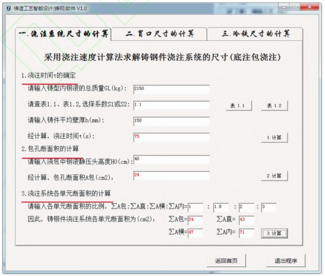
The gating system of sand casting mainly includes five parts: the sprue cup, the sprue groove of the sprue, the transverse sprue, and the inner sprue. As a channel for high-temperature metal liquid in the ladle to flow into the mold cavity, the design of the gating system of sand casting plays a crucial role in controlling sand casting defects. The material of the lining plate is chromium molybdenum alloy steel, with a single piece weight of 7.25x10²kg, which belongs to medium-sized cast steel parts. In the pouring process of V-method casting, in order to avoid coating detachment caused by excessive flow rate of molten metal washing the mold cavity, it is necessary to ensure a smooth filling process. Therefore, bottom pouring package pouring and open pouring system are adopted. Using the pouring speed calculation method to calculate the dimensions of each unit, first calculate the pouring time and pouring speed of the sand casting based on its quality and structural characteristics. Then, select the corresponding package hole according to the pouring speed, and finally, root! Determine the cross-sectional dimensions of each unit of the pouring system based on the size of the package hole. Figure 1 shows the calculation interface of the pouring system size in the “Intelligent Design of Casting Process (Steel Casting)” software. This interface divides the design of the pouring system into three steps: determining the pouring time t, calculating the cross-sectional area of the ladle hole, and calculating the cross-sectional area of each unit of the pouring system.
1.1 Calculation of pouring time
The design of the V-method casting pouring system should follow the principle of “seeking speed while maintaining stability”. “Stability” refers to the smooth flow of the molten metal in the mold, and “speed” refers to the rapid rise of the free liquid surface of the molten metal in the mold. In order to reduce the baking time of the EVA film on the surface of the cavity during the V-method casting process and avoid the collapse of the box caused by the decrease of negative pressure inside the mold, it is necessary to accelerate the rising speed of the metal liquid and shorten the casting time as much as possible.
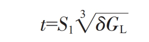
In the formula, t is the pouring time (s); G is the total mass of the molten metal in the mold (kg), including the pouring system, riser, and sand casting mass. 8 is the average wall thickness of the sand casting (mm): S is the calculation coefficient.
The production rate of steel castings within the weight and thickness range of sand castings is generally around 61% to 67%. Therefore, the total mass G of the molten metal in the mold is preliminarily determined to be 2150 kg (one box with two pieces). The average wall thickness of sand castings is 8, and the thickness of the middle part of the lining plate lifting strip is 150 mm. According to the values of G and 8, refer to Table 1. S and the value is 1.1.
| Average wall thickness of castings S/mm Steel liquid weight G/t | <25 | >25~40 | >40-60 | >60 |
| 1.0-6.0 | 1.3 | 1.2 | 1.1 | 1.0 |
| >6.0-10.0 | 1.4 | 1.3 | 1.2 | 1.1 |
Therefore,

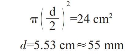
1.2 Calculation of the cross-sectional area of the package hole
(1) Calculation of pouring speed v
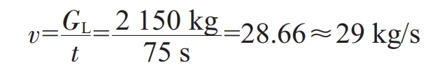
Considering the opening degree of the ladle hole plug during pouring steel liquid, in order to ensure that the required speed of the sand casting is achieved during the pouring process, the pouring speed p of the ladle hole should be 1.3 times the required pouring speed of the sand casting, that is:

(2) Calculation of the cross-sectional area A of the package hole
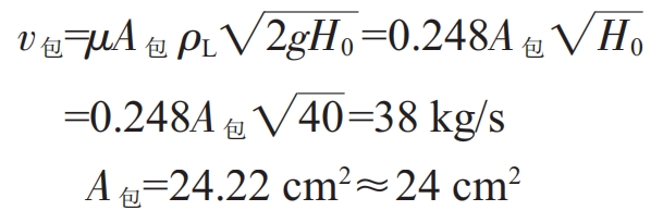
In the formula, “is the pouring speed of the package hole (kg/s);”; μ The loss coefficient is usually taken as 0.8; 4 “is the cross-sectional area of the ladle (cmm?); p is the density of the molten steel (kg/cm); g is the gravitational acceleration, usually taken as 9.8 m/s?: H, is the static pressure head height of the molten steel in the ladle, and the average value of the pouring process is 40cm.”.
Therefore, the diameter d of the package hole is:
1.3 Calculation of cross-sectional area of each unit
When calculating the cross-sectional area of each unit using bottom pouring bags, an open pouring system is used, and the proportion of cross-sectional area of each unit is generally as follows:
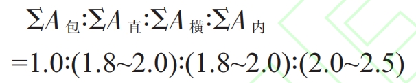
In the formula, ∑ A represents the total cross-sectional area of the ladle hole (cm ^ 2); zA represents the total cross-sectional area of the sprue (cm ^ 2); Σ 4 “is the total cross-sectional area of the transverse sprue (cm ^ 2): ∑ 4W is the total cross-sectional area of the inner sprue (cm ^ 2).
To alleviate heat concentration and reduce the flow rate of the melt, the total cross-sectional area of the inner runner in the V-method casting system needs to be about 30% larger than that in ordinary sand casting A. It can be appropriately increased without being limited by the proportion in the formula, and based on this, the proportion of the cross-sectional area of each unit in the pouring system is adopted Σ A: ∑ A: ∑ A: ∑ Aw=1:1.8:2:3. Therefore, ∑ A-44 cm ^ 2;
ZA:=48 cm; ∑ Aw-72 cm ‘.
Figure 2d is a schematic diagram of the lining plate pouring system (using one box with two pieces). The sprue is designed as a conical shape along the flow. If the sprue is designed as a cylinder, when a certain flow rate of metal liquid flows from the top of the sprue to the bottom, a low-pressure liquid flow area will be formed at the bottom of the sprue due to the increase in liquid flow velocity. The low-pressure liquid flow zone will suck in air, causing the metal liquid wrapped in gas to flow into the mold cavity, thereby forming sand casting defects. The design dimensions of the sprue are shown in Figure 2a.
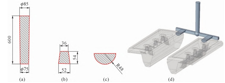
When the metal liquid flows through the junction of the vertical and horizontal runners at a certain flow rate, the flow direction of the liquid will undergo a large angle deviation. In order to reduce the impact of liquid flow on the pouring system and avoid turbulence and agitation of the metal liquid, a liquid storage tank, namely the sprue groove, is designed at the lower end of the sprue. The diameter of the sprue groove is designed to be twice the diameter of the bottom of the sprue, and its height is designed to be 1.5 times the height of the transverse sprue.
The cross-section of the transverse runner is designed as a trapezoid to collect the slag on the metal liquid surface inside the transverse runner and prevent the inner runner from solidifying and blocking the pouring channel during the pouring process. The length of the transverse runner is appropriately extended to be greater than the distance between two inner runners. During the pouring of the metal liquid, the slag on the surface of the molten metal inside the transverse runner will be transported and aggregated to its tail. The design dimensions of the transverse runner are shown in Figure 2b.
In order to take into account the advantages of both top and bottom pouring internal gates, the guiding position of the internal gate is selected at the parting surface of the lining sand casting, which is the plane where the substrate and lifting bar intersect. The pouring system of the parting surface is equivalent to top pouring for the lower box cavity and bottom pouring for the upper box cavity. This design effectively reduces the height of metal liquid falling in the cavity. Design the cross-section of the inner runner as a semi-circular shape, with the design dimensions shown in Figure 2c.
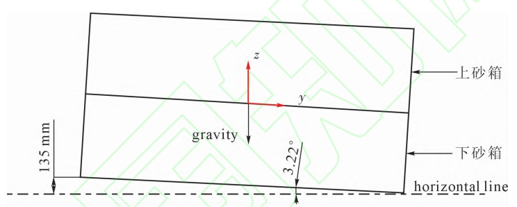
This pouring system has a simple design, good economy, and is easy to remove sand castings after opening the box. Setting the inner runner on the end face of the lining plate can effectively prevent inclusions caused by the erosion of the mold cavity wall surface by metal liquid flowing into the mold. The substrate of the lining sand casting is located on the upper mold. In order to reduce the projection area of high-temperature metal liquid radiation heat during pouring, an inclined pouring process is adopted. Lift the end of the sand box away from the pouring system, so that the bottom surface of the sand box forms a 3.22 ° angle with the horizontal plane, as shown in Figure 3. The metal liquid will be drawn from the low position of the mold cavity, and the free liquid level will gradually rise, ensuring the negative pressure of the mold.
2. Intelligent design of heating riser
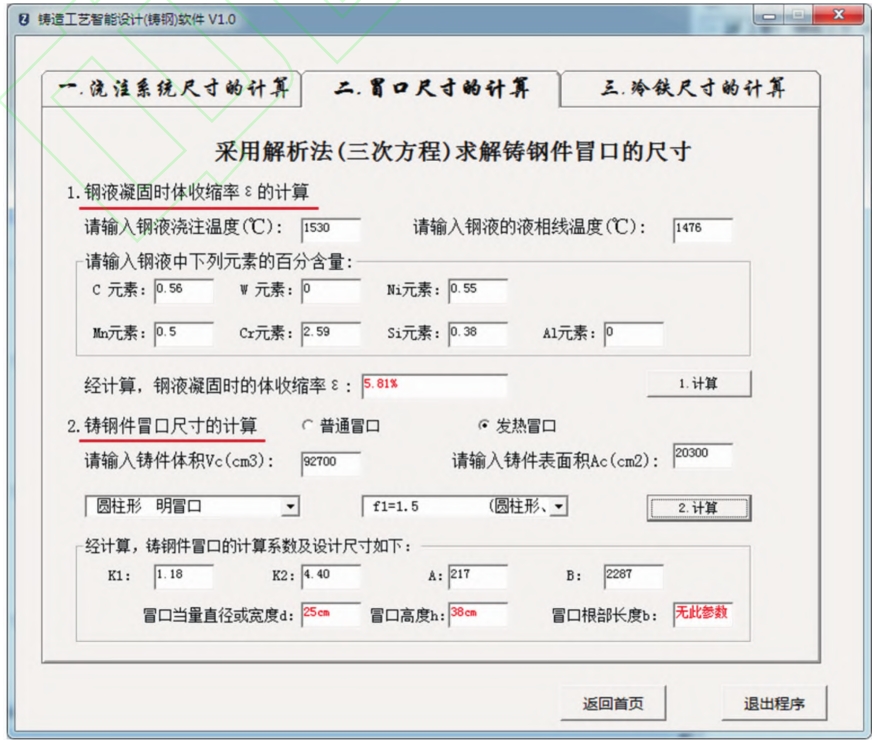
A riser is a liquid storage tank designed to compensate for the solidification shrinkage of sand castings. Solving the riser size of steel castings using analytical methods (cubic equations) is a method that requires only simple mathematical tools to solve the equivalent diameter d of the riser. Figure 4 shows the riser size calculation interface of the “Intelligent Design of Casting Process (Steel Casting)” software. The interface divides the calculation of riser size into two steps: calculating the volume shrinkage rate s during steel solidification and calculating the riser size of steel castings.
2.1 Calculation of body shrinkage rate during solidification of molten steel
The molten metal after pouring into the mold will undergo three interrelated shrinkage stages: liquid shrinkage, solidification shrinkage, and solid shrinkage during the cooling process from pouring temperature to room temperature.
In the liquid shrinkage stage, the molten metal inside the mold cools from the pouring temperature to the liquidus temperature. At this stage, the molten metal is in a complete liquid state. As the temperature decreases, the volume of the molten metal continuously decreases, causing the free liquid level of the molten metal inside the mold to continue to decrease. The liquid shrinkage of metal liquid is usually described by the volume shrinkage rate, and its calculation formula is:
During the solidification shrinkage stage, the molten metal in the mold cools from the liquidus temperature to the solidus temperature, and the aggregation state of the molten metal will change during this stage. As the temperature decreases, the aggregation state of the metal liquid will gradually change from liquid to solid, the distance between atoms will decrease, and the metal liquid will undergo solidification shrinkage.
In the solid shrinkage stage, the metal inside the mold cools from the solidus temperature to room temperature, which is manifested macroscopically as a decrease in the size of the sand casting in all directions. The solid shrinkage of the metal is usually described by the linear shrinkage rate. For pure metals and alloys with eutectic compositions produced at specific temperatures, solid shrinkage occurs after complete solidification of sand castings. For alloys with deviation from the common component and a certain temperature interval, solid shrinkage can occur when the branches overlap to form a continuous skeleton in the sand casting.
Shrinkage rate of liquid steel shrinkage body ε The main influencing factors are the alloy composition and pouring temperature. Based on this, scholars from the University of Science and Technology of China, such as Xu Yunxiang and Yang Zhenhe, proposed the following formula for calculating the volume shrinkage rate e of sand casting structural steel during liquid shrinkage:

In the formula, “is the mass fraction of carbon in the steel liquid;” is the mass fraction of alloy element i in the steel liquid; K is the coefficient of influence of alloying element i on the shrinkage rate of the steel liquid (refer to Table 2); K is the coefficient of influence of pouring temperature on the shrinkage rate s of the steel liquid, usually taken as 0.014% for casting structural steel; 7 is the pouring temperature of the steel liquid (℃); T is the liquidus temperature of the steel liquid (℃).
| Alloying element | W | Ni | Mn | Cr | Si | Al |
| Body shrinkage coefficient Ki% | -0.53 | -0.0354 | +0.0585 | +0.12 | +0.13 | +1.70 |
According to the formula, referring to the chemical composition of chromium molybdenum alloy steel in lining sand casting, the body shrinkage rate e of chromium molybdenum steel liquid can be solved. After calculation, the value of e is 5.81%.
2.2 Calculation of heating riser size
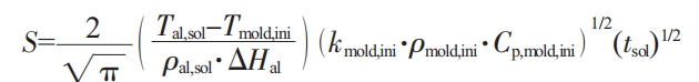
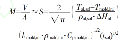
During the solidification process of sand castings, due to the feeding effect of the riser on the sand castings, the molten metal in the riser will flow towards the castings. When the solidification of sand castings is completed, the volume of molten metal in the riser will decrease from the initial to V- EVc. Usually, the shrinkage hole is located in the middle of the riser, so it is speculated that the heat dissipation capacity of the top and side of the riser is equivalent. At the same time, the heat dissipation surface area of the riser before solidification is 4, which is approximated to the heat dissipation surface area at the end of solidification. Therefore, the actual modulus M of the riser at the end of solidification is:
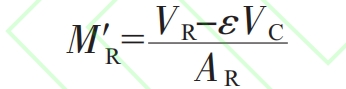
In the formula, “M” is the actual modulus of the riser at the end of solidification (cm); V is the volume of the riser (in cm?); 1- is the volume of the reduced part of the sand casting (in cm?: A: is the heat dissipation surface area of the riser (in cmn); E is the volume shrinkage rate of molten steel solidification.
The metal liquid fed from the riser into the sand casting will increase the density of the sand casting. If the density change is considered as a volume change (conservation of mass law), the equivalent volume at the end of solidification of sand castings is (l+e) Vc. Therefore, the actual modulus M of the sand casting being filled and shrunk at the end of solidification is:
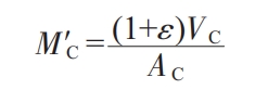
In the formula, Nc is the actual modulus (cm ^ 2) of the sand casting being filled and shrunk at the end of solidification; Ac is the surface area (cm ^ 2) of the sand casting to be filled.
By approximating the actual modulus of the riser at the end of solidification with the actual modulus of the sand casting being filled, i.e. N ‘=Nc, we can obtain:
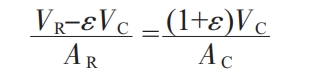
In summary, the equivalent diameter d of the heating riser is 25 cm, and the height h of the riser is 37.5 cm. Based on the cubic equation of the size of the exposed heating riser for steel castings, the design dimensions were obtained. The HLEM-C-S300 exposed heating riser was selected, with a heating energy of 1650 · kg, a heating temperature of 1200 ℃, and a heating time of 240 seconds.
3. Determination of Riser Placement Position
Whether the riser can successfully eliminate internal shrinkage and porosity defects in sand castings requires not only appropriate and reasonable design of the riser size, but also the correct selection of the riser’s safety position. The traditional view is that in order to improve the feeding efficiency of the riser, it is necessary to follow the solidification order of the sand casting, and the safety position of the riser should be selected at the position with the maximum modulus of the sand casting. However, a large number of production practices have shown that if the riser is directly set at the maximum modulus of the sand casting, it will lead to the generation of contact heat joints. Only by setting the riser slightly deviating from the maximum modulus of the sand casting can the shrinkage and porosity defects inside the sand casting be effectively eliminated. To obtain the accurate distribution of modulus in various parts of the sand casting, Chvoriov thermal modulus is used as the modulus of the sand casting.
For sand casting of semi infinite flat plates, the relationship between the solidification layer thickness S and the solidification time center is:
In the formula, S is the thickness of the solidification layer (cm); T is the solidus temperature of the alloy (K); 7… is the initial temperature of the mold (K); P is the density of the alloy at the solidus temperature (g “cm ²; H is the enthalpy change from the initial temperature of the alloy to the solidus temperature (J · kg ‘); hmmn is the thermal conductivity at the initial temperature of the mold (W · m’ · K ‘); pma is the density at the initial temperature of the mold (g · cm’; caa is the specific heat capacity at the initial temperature of the mold ① · kg ‘· K’);.. Is the solidification time of the casting (s).
The formula is the relationship between the thickness of the solidification layer and the solidification time under one-dimensional solidification conditions, given the thermal properties parameters of the mold and casting. Therefore, it is extended to castings with complex shapes. It is known that the contour of the inner surface of the mold will have a certain impact on the heat transfer ability of the mold. In contrast to the flat mold wall, the heat flow will diverge when passing through the concave mold wall and converge when passing through the convex mold wall. Therefore, the heat transferred by the mold through the concave mold wall per unit time will be more than that through the convex mold wall. For molds with simple wall profiles, this difference can be ignored, assuming that the heat transfer capacity of the mold is independent of its cavity profile. According to this assumption, the thickness S of the solidification layer of the casting can be replaced by the ratio VA of the casting volume V to the heat transfer surface area 4 of the casting, i.e.:
In the formula, is the volume of the casting (cm: is the heat dissipation surface area of the casting (cm ^ 2); Y is the thermal modulus (cm) determined by Chvorinov’s theorem.
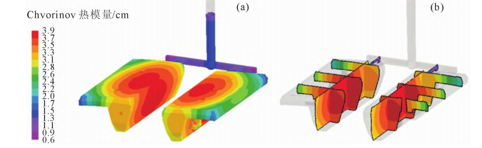
The formula is the Chvorinov theorem proposed by Czech engineer Nikolaj Chworinov in 1940. In order to quickly and accurately obtain the distribution of thermal modulus in each part of the lining plate casting, the FOCAST numerical simulation system is used to simulate and analyze the casting process of the lining plate casting (excluding the riser). Extracting data such as mold, thermal properties of castings, and solidification time at various locations of castings, and substituting them into the calculation formula of Vommov thermal modulus, the distribution cloud map of Chvorinov thermal modulus of village plate castings is obtained, as shown in Figure 5. The maximum value of the thermal modulus of the casting is 39cm, and its distribution pattern is that the thermal modulus gradually increases from the outer edge of the lining plate to the center, with the maximum value of the thermal modulus at the center of the casting. Based on this, it is determined to set a heating riser near the center of the surface on the substrate.
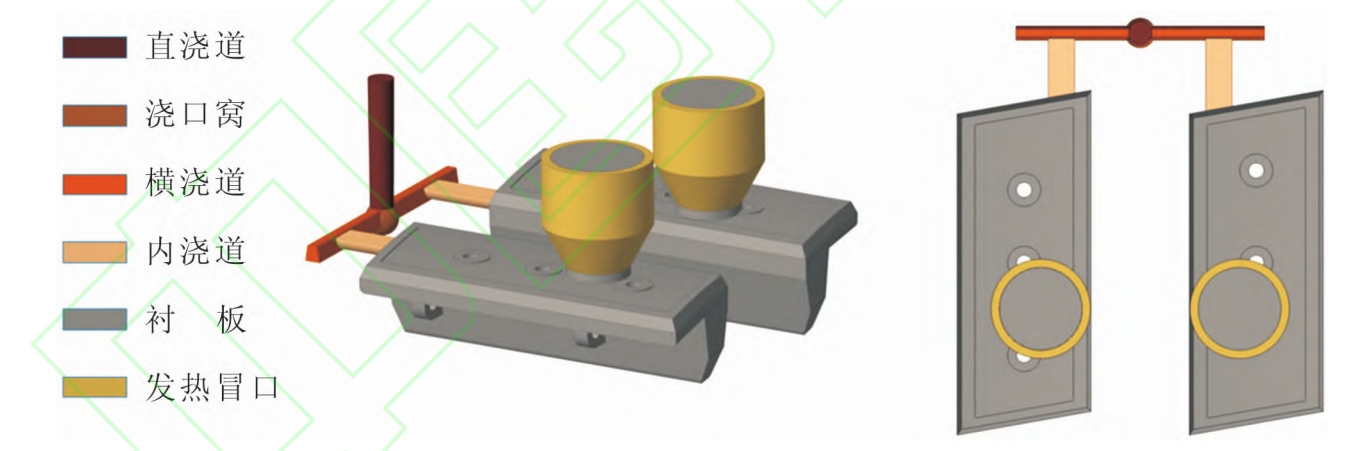
Therefore, the new casting process for the lining plate is shown in Figure 6, and its theoretical process yield is about 85.2%.