
Compared with traditional sand casting technology, the lost foam casting process has advantages such as precise casting size, good repeatability, flexible production, and good internal quality. Since the patent expired in 1980, lost foam casting technology has experienced rapid development worldwide. Nowadays, the lost foam casting technology is becoming more mature both domestically and internationally, with a wide range of applications, especially suitable for complex shell components. This article focuses on the application of lost foam casting technology in the production of shell products, and points out the main problems of current lost foam casting technology in the production of shell products. It also emphasizes several casting defects and their causes analysis, as well as rectification measures. It is mainly manifested in that during the casting process of the mold cluster, with the foam gasification and accompanied by the flow and solidification of the liquid metal, there will be casting defects such as sand hole and sand washing when producing such castings as flywheel housing. ZHY Casting takes flywheel shell castings and other products as examples to introduce the causes and improvement measures of casting defects related to lost foam casting.
1. Analysis of the causes of sand sticking casting defects in flywheel housing castings
Clay sand casting defect is a type of casting defect formed by the bonding of molten metal and molding sand on the surface of the casting during the pouring process. Unreasonable placement, structural design, or process design of flywheel shell castings in lost foam casting can lead to mold clusters being unable to vibrate in the sand box, resulting in sand sticking casting defects.
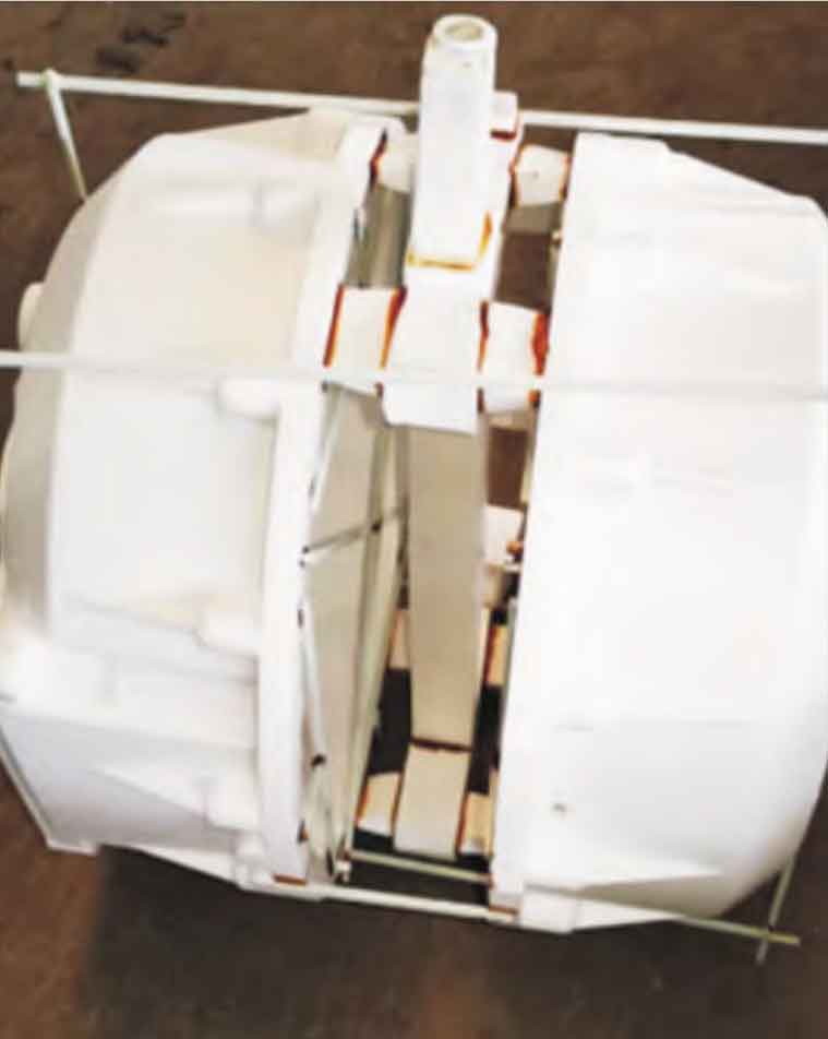
The currently produced 9661 lost foam casting flywheel housing is made of HT250 material, weighs approximately 22 kg, has a contour size of 440 mmx440 mmx220 mm, and a product wall thickness of 5mm. This product has issues such as large size area, thin foundation wall thickness, and easy deformation. The existing process is shown in Figure 1, with an inner runner size of 50mm long x 30mm high x 6mm wide. The temperature at which the molten iron is discharged from the furnace is 1460-1470 ℃ (with the melting equipment being an electric furnace), the pouring temperature is 1430-1440 ℃, the vacuum degree is -0.025 MPa, and it is not covered with film and does not maintain pressure. The main casting defects is sand inclusion at the top of the inner cavity of the flywheel housing in lost foam casting, with a scrap rate of 20%.
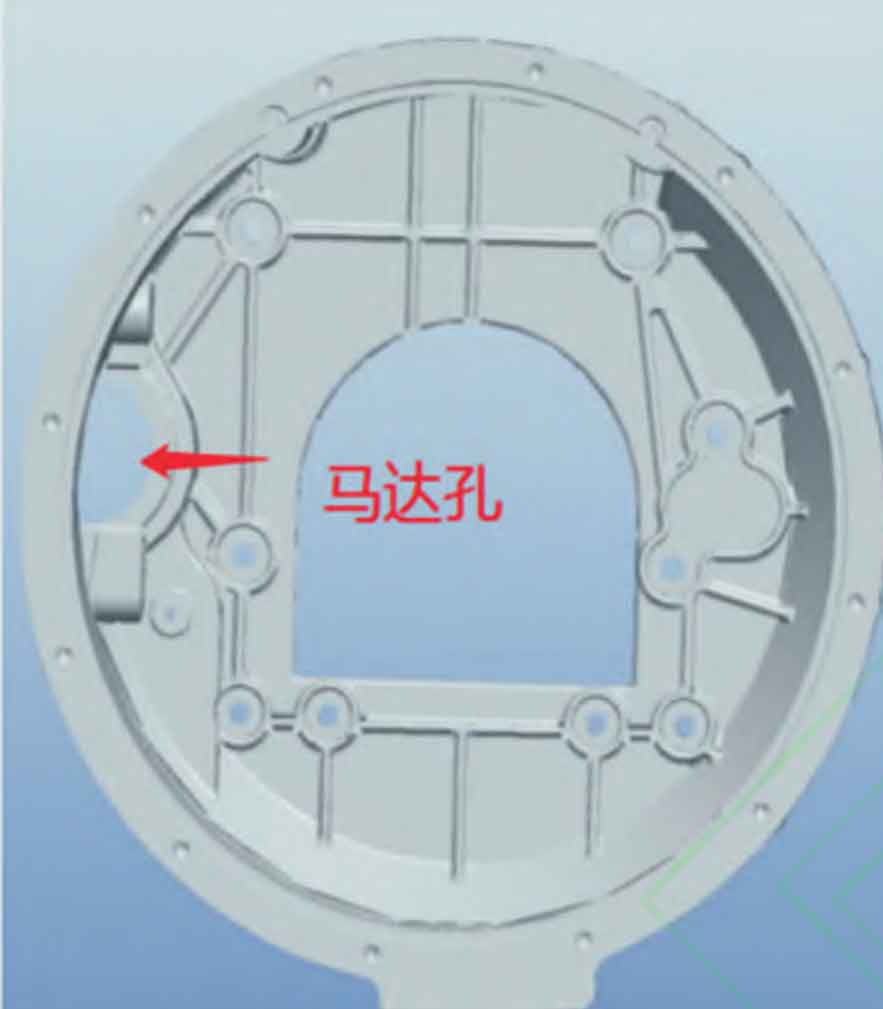
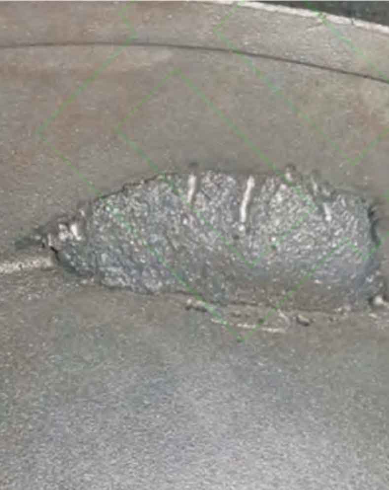
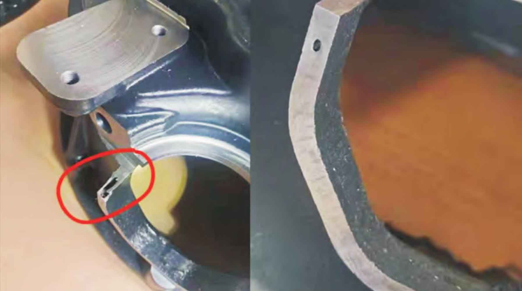
The existing process motor hole is located below (Figure 2), and the top of the inner cavity of this product often experiences sand sticking issues, as shown in Figure 3. This is because the top angle is greater than 90 °. The molding sand cannot fill the mold cluster during vibration, and the top molding sand is relatively loose. During the filling process of molten iron, local metal and molding sand adhere to each other, resulting in sticky sand.
1.1 Analysis of flywheel shell sand sticking
The 9661 lost foam casting flywheel shell exhibits a mechanical mixture of sand particles and metal adhering to the surface of the shell. When cleaned, the surface has a metallic luster, which is a unique manifestation of mechanical sand adhesion. The main influencing factors are the compactness of the molding sand during molding, the fire resistance of the coating, the pouring temperature, and the coating thickness. Except for the sand sticking on the top of the casting, the other positions of the lost foam casting flywheel housing are normal without any sand sticking marks. Therefore, it is considered that there is a problem with the compactness of the molding sand, and the analysis reason is:
① The top of the flywheel shell in lost foam casting cannot be filled with enough sand or the existing state sand cannot be compacted;
② The gap between the two lost foam casting flywheel shells is too small, resulting in weak sand strength.
1.2 Control measures
Based on the mechanism of sand sticking in castings and its influencing factors, the following measures are mainly taken to solve it.
(1) Adjust the placement of the white mold according to the product structure, with the motor hole of the lost foam casting flywheel housing facing upwards to facilitate sand filling and ensure that there is sufficient sand at the top of the lost foam casting flywheel housing.
(2) Increase the distance between the two lost foam casting flywheel shells from the original 80 mm to 120 mm, ensuring sufficient distance between the two mold clusters and ensuring the compactness of the molding sand.
1.3 Production validation
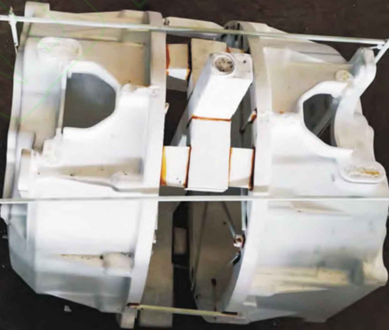
A root cause analysis was conducted on the compactness problem of the flywheel shell sand in lost foam casting, and two measures, including product placement method four and combination spacing, were taken to improve the existing combination process. During its normal production process, while ensuring that the variable factors such as immersion coating process, pouring temperature, and vacuum extraction remain unchanged, production validation was carried out again from small to large batches, and the casting defects of the sticky sand casting was zero. By adjusting the above measures, the final process is shown in Figure 4, achieving the goal of completely solving the sand sticking casting defect on the top of the lost foam casting flywheel shell.
2. Analysis of the causes of porosity casting defects in flywheel housing castings
When the molten iron enters the mold cluster, the white mold undergoes gasification and decomposition to generate a large amount of gas and residue, which cannot be discharged from the body in a timely manner, resulting in the formation of pores on the surface of the casting. The appearance of pores is related to pouring temperature, coating permeability, pouring speed, etc.
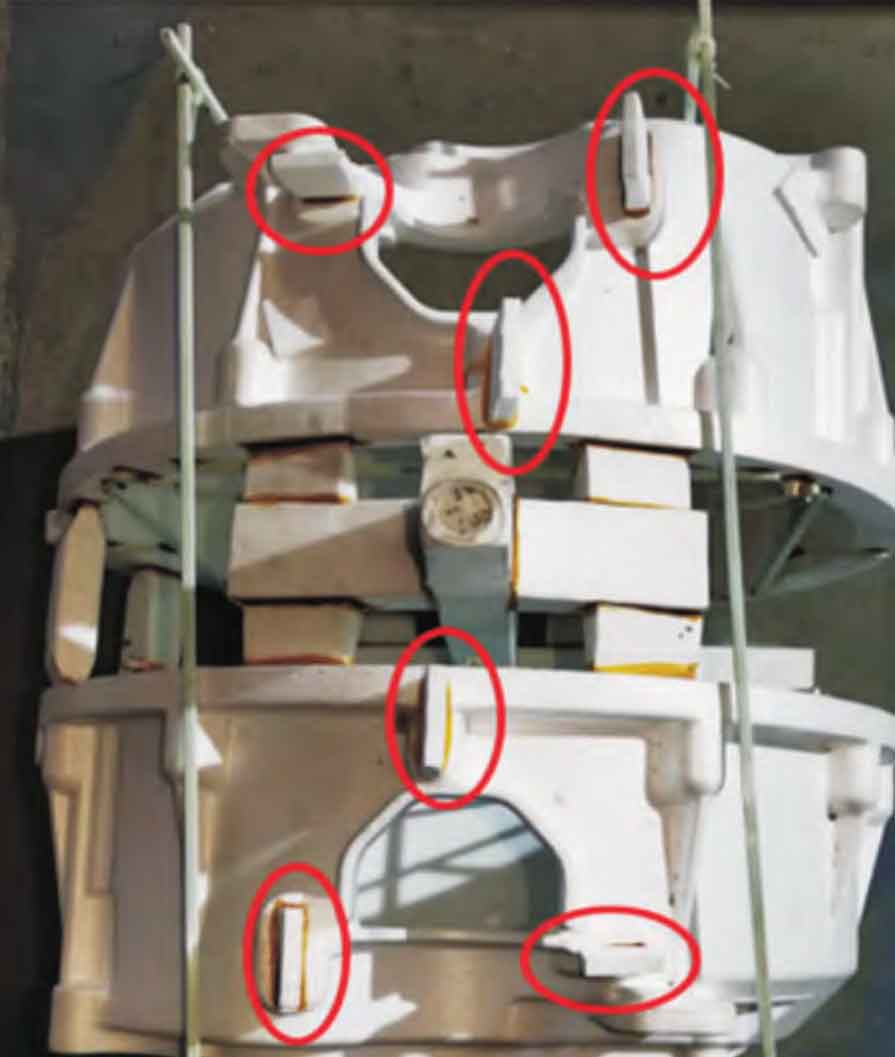
The product is a lost foam casting flywheel shell of SAIC Maxus, with casting defects such as air holes, as shown in Figure 5. The iron liquid is discharged from the furnace at a temperature of 1460~1470 ℃ (melting equipment is an electric furnace), poured at a temperature of 1430~1440 ℃, vacuum at -0.025 MPa, without film coating or pressure retention. The main casting defect is the motor hole air hole located at the top of the product, and the proportion of scrap accounts for 30%.
2.1 Influencing factors
The casting defects of this porosity is manifested as normal appearance inspection on the surface or near the surface of the casting, but there are smooth pores of varying sizes on the surface after processing, and the pore walls also have oxidation colors. The location of pores is mainly concentrated at the top of the product, which is a unique manifestation of subcutaneous pores. The main influencing factors are:
① In terms of pouring temperature, when the pouring temperature is low, the foam is not fully burned and the gas is not completely discharged, forming pores under the skin;
② ) In terms of local coating thickness, the motor hole coating is too thick, and the gas cannot be discharged after foam combustion, forming pores:
③ In terms of vacuum degree, the vacuum is too small, and the body cannot be evacuated in time, forming pores;
④ The process design is unreasonable. The top of the lost foam casting flywheel housing lacks an exhaust port, and the gas is concentrated at the top of the body and not completely discharged, forming pores.
2.2 Control measures
Based on the mechanism of porosity formation in castings and its influencing factors, the following measures are mainly taken to solve it.
(1) Raise the pouring temperature from 1430-1440 ℃ to 1450-1460 ℃, and pour 10 sets.
(2) Reduce the coating thickness here, currently reducing the coating thickness from 2.0mm to 0.5mm, and pour 10 sets.
(3) Increase the vacuum degree and pour 10 sets from -0.025 MPa to -0.045 MPa.
(4) Add exhaust plates at the motor hole, 50mm (length) x 30mm (height) x 5mm (width), and pour 10 sets.
2.3 Production validation
A root cause analysis was conducted on the problem of air holes in the flywheel shell of lost foam casting, and four measures were taken to improve the existing process parameters, including product pouring temperature, product coating thickness, product pouring vacuum degree, and adding exhaust fins. During the process testing, while ensuring that the other three process parameters remained unchanged, the controlled variable method was used for the experiment. Among them, Plan 1 increased the pouring temperature, produced and processed 20 pieces and 4 holes, The proportion of motor holes and air holes is 20%; Option 2 is to reduce the coating thickness by producing and processing 20 pieces, with 5 air holes and a 25% proportion of motor holes; Plan three is to improve the vacuum degree by producing and processing 20 pieces with 3 air holes, and the proportion of motor holes and air holes is 15%. Plan four adds exhaust fins, producing and processing 20 pieces with 0 air holes, and the proportion of motor holes and air holes is 0%. After testing, scheme four yielded the best results. Subsequently, it was verified that the processing was normal by converting from small batches to large batches. By adjusting the above measures, the goal of completely solving the motor hole porosity was achieved. The final process is shown in Figure 6.
3. Cause analysis of sand punching casting defects in connecting rod frame castings
During the pouring process, the vertical sprue, horizontal sprue, and internal sprue in the mold cluster pouring system are not completely closed, especially the vertical sprue, which is prone to forming siphons and leading to sand flushing casting defects. The product pouring system design is unreasonable, the filling is not smooth, the local pressure in the internal sprue is high, and the coating is broken due to the flushing of molten iron, resulting in the sand entering the mold cluster cavity with the molten iron, which can also cause sand flushing casting defects.
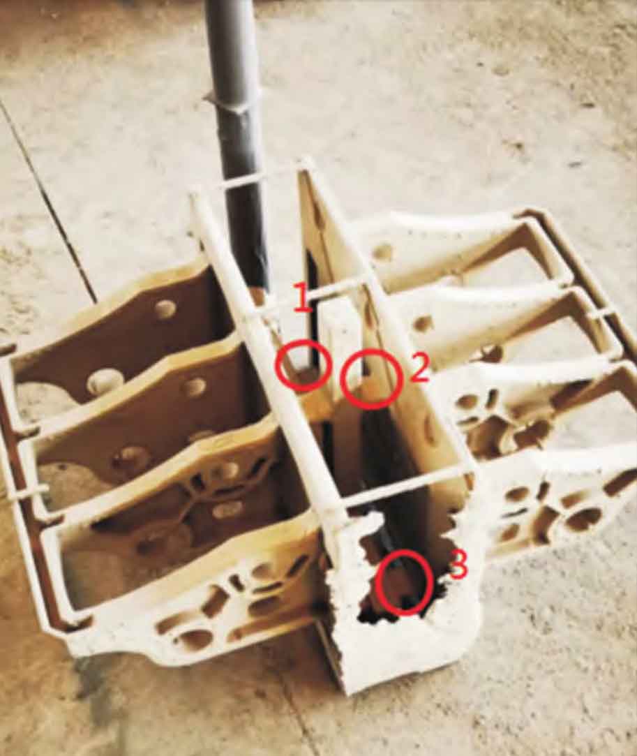
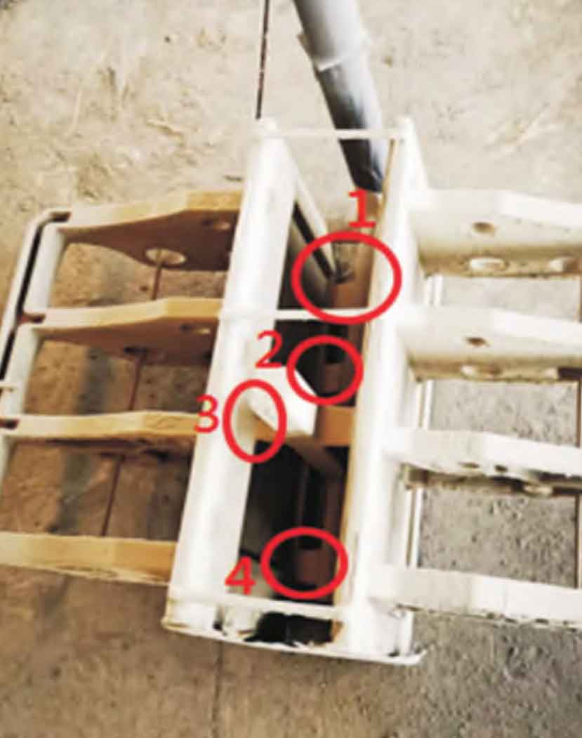
Figure 7 shows the pouring system diagram of the lost foam casting connecting rod frame casting. The product material is HT200, weighing about 50 kg, with a contour size of 572 mm x 380 mm x 348 mm and a bottom plate thickness of 12 mm. The existing process involves introducing molten iron through a 3-point inner gate on the side, with an inner gate size of 60 mm (length) x 30 mm (height) x 6 mm (width). The process parameters are the temperature of molten iron being taken out of the furnace from 1460 to 1470 ℃ (the melting equipment is an electric furnace), pouring temperature from 1430 to 1440 ℃, vacuum pressure of 0.03 MPa, no film coating, no pressure retention, and the main casting defect is sand flushing, which is concentrated in the vicinity of the bottom inner runner (Figure 8), with a waste proportion of 20%.

3.1 Influencing factors
The defects in sand flushing casting are located at the bottom of the mold cavity in the straight line of the gate and the area where molten iron flows into the mold cavity in the inner gate. The nodules formed by mixing sand particles with metal in this area are unique manifestations of sand flushing, and the main influencing factors are:
① The strength of the inner runner coating is low, and the coating cracks due to the erosion of molten iron;
② The high pressure on the inner runner causes the coating to break;
③ During the pouring process, the molten iron sprayed back severely, causing the coating to break.
However, during the pouring process of this product, the molten iron pouring is smooth and there is no backspraying phenomenon, so the first two factors are mainly considered
3.2 Control measures
Regarding the mechanism of sand flushing in lost foam casting of connecting rod frame castings, the following measures are mainly taken to solve the problem based on its influencing factors.
(1) The existing process involves two coats of coating immersion, with a coating thickness of 1.5 mm and an additional dip coating process for the inner runner. The coating thickness is 2.2 mmn.
(2) Increase the number of internal runners and add another internal runner of the same size at the bottom two points.
3.3 Production validation
A root cause analysis was conducted on the sand flushing problem of the lost foam casting connecting rod frame casting, and two measures were taken to improve the existing process parameters, including the thickness of the inlet coating and the number of inlet ports. During the process testing, while ensuring that the pouring temperature, vacuum degree and other influencing parameters remain unchanged, production validation was carried out from small to large batches. Among them, Plan One involves adding one coat of coating to the inner runner, producing 50 pieces, of which 6 pieces were sandblasted, accounting for 12%; Option 2 is to add an inner runner at the bottom, producing 50 pieces and flushing 0 pieces. After verification, Scheme 2 is the best. Is the processing normal after converting from small batches to large batches. This process optimization adopts 3 inner runners at the bottom and 1 inner runner at the top, which can play a role in diverting and reducing pressure. The cross-sectional area size of a single sprue is 60 mmx8 mm, the area of a straight sprue (diameter 50 mm round pipe) is 50 mmx40 mm, and the area of a transverse sprue is 1 960 mm ^ 2:2 000 mm ^ 2:1 920 mm ^ 2, which basically meets the 1:1:1 condition and achieves the goal of completely solving the sand flushing casting defects of the lost foam casting connecting rod frame casting. The final process is shown in Figure 9.
4. Conclusion
(1) In the process of developing new products, it is necessary to cleverly avoid casting defects through process design based on their causes. (2) In the process of promoting process validation, the quantity of products promoted varies from small to large, from small to large batches, in order to avoid significant losses caused by insufficient process attendance,
(3) In the process of process validation, progress is made step by step from five aspects: grasping the current situation, analyzing the causes, formulating plans, implementing countermeasures, and confirming the effects, ultimately achieving the goal of thoroughly solving problems.