
A machine-tool bed fixes the geometric relationship between the spindle, the guideways and the workpiece, so its casting has to satisfy three requirements at once: stiffness under cutting loads, damping of vibration, and dimensional stability that persists after machining. The bed discussed here is a thin-walled, heavy-section iron casting with a maximum envelope of 2400 mm × 1280 mm × 700 mm, a nominal wall of 15 mm, a section height of 630 mm and a poured mass of 1900 kg. Thin walls separated by thick ribs and guideway pads cool at very different rates, which is where shrinkage porosity and distortion originate. In a conventional sand mould the additional error source is the core package: each core is positioned in a core print, and the accumulated mismatch between cores shows up directly as wall-thickness scatter and as dimensional error across the bed.
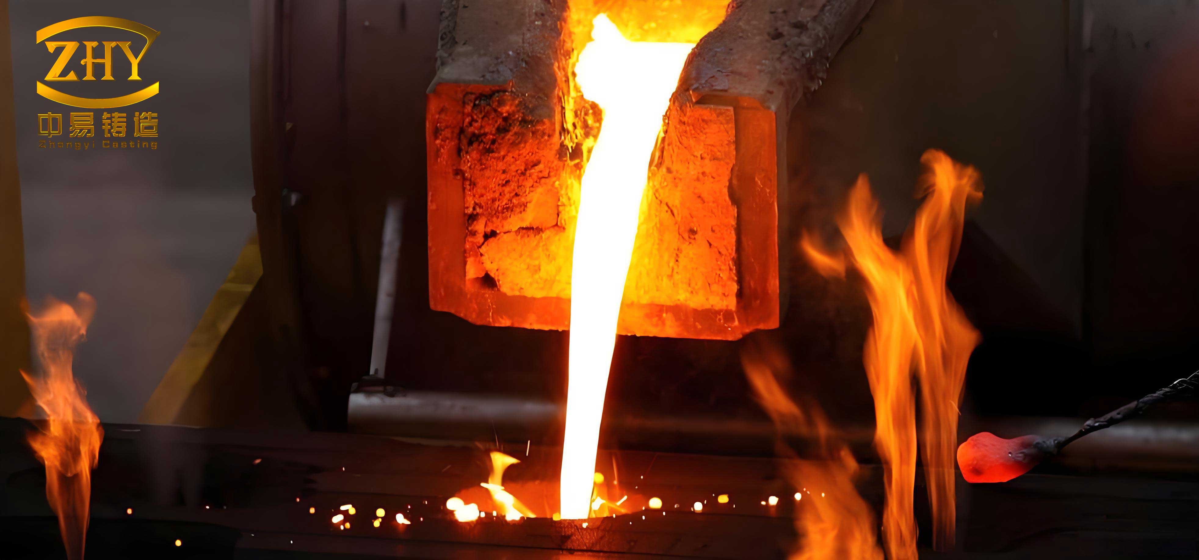
Lost foam casting removes that error chain rather than compensating for it. The mould cavity is a sacrificial expanded-polystyrene (EPS) replica of the part; the replica is coated, embedded in dry, unbonded silica sand, compacted by vibration, and then filled with liquid iron, which decomposes and displaces the polymer. Because the pattern is consumed, there is no parting plane, no draft angle and no core to be located or clamped. Complex internal pockets and undercuts are formed by the pattern itself, so the dimensional accuracy of the casting is decided mainly by the accuracy of the foam assembly and by the stability of the sand bed.
Pattern fabrication and moulding practice
Pattern density is the single most influential pattern variable. A density of 20 kg/m³ is used for these beds: low enough to limit the volume of decomposition gas that must escape through the coating during filling, yet high enough for the machined pattern to keep its shape during handling and compaction. Patterns are built by bonding thick EPS block and machining it under numerical control, and the cutter shank diameter is kept small, since an oversized tool tears the bead structure and leaves marks that are reproduced on the casting surface. Long beds are sectioned for transport because EPS patterns are fragile, and the block stock used here reaches 8 m in length.
After coating and drying, the pattern is packed in a flask and the sand is compacted by vibration while a vacuum is drawn through the sand. Compaction uniformity matters as much as pattern accuracy: sand that is not densely and evenly packed around a 15 mm wall will move when the metal enters, and the resulting deflection appears as wall-thickness variation that no pattern tolerance can correct.
Gating and filling design
Filling is organised through a split gating system with 25 ingates distributed along the bed, so that the flow field, the pressure field and the temperature field stay as even as possible over a 2400 mm length. A pouring time of 55 s was selected together with a static head of 600 mm. The resistance coefficients of the ingate, runner and sprue are 0.4, 0.5 and 0.5 respectively, and the gating system is proportioned at a sprue : runner : ingate cross-section ratio of 1 : 2 : 2.
Because the sprue and the ingates behave as two orifices in series, the average pressure head at the ingate is obtained from the two-orifice discharge relation
$$h_p=\frac{K_2^{2}\,H_p}{1+K_1^{2}+K_2^{2}}$$
where $H_p$ is the average head at the small orifice, $h_p$ the average head at the large orifice, and $K_1$ and $K_2$ are the ratios of effective flow areas in the gating chain. The calculation gives an ingate head of 14.2 cm. The total sprue area then follows from the flow-rate relation
$$S=\frac{G}{\rho\,\tau\,\mu\sqrt{2g\,h_p}}$$
with $G$ the poured mass, $\rho$ the density of liquid iron, $\tau$ the pouring time, $\mu$ the discharge coefficient (taken as 0.5) and $g$ the gravitational acceleration. The resulting areas are 36.5 cm² for the sprue, 73 cm² for the runner and 73 cm² for the ingates. These are realised as a single 60 mm × 60 mm sprue, two runners of the same section, and 25 ingates of 10 mm × 30 mm; the ingates as built give 25 × 300 mm² = 75 cm², which matches the calculated 73 cm² within the rounding of the design.
| Element | Count | Section | Calculated area | Area ratio |
|---|---|---|---|---|
| Sprue | 1 | 60 mm × 60 mm | 36.5 cm² | 1 |
| Runner | 2 | 60 mm × 60 mm | 73 cm² | 2 |
| Ingate | 25 | 10 mm × 30 mm | 73 cm² (75 cm² as built) | 2 |
Thermal and chemical control
Pouring temperature is the main lever on shrinkage porosity in a wall of 15 mm. An excessively hot pour enlarges the liquid shrinkage that has to be fed and therefore enlarges the cavities it leaves behind; the temperature adopted for this bed is 1350 °C, high enough to keep the thin sections from misrunning and cold shuts during a 55 s fill but low enough to limit the volume deficit at the hot spots.
Phosphorus is controlled because it embrittles the casting skin and widens shrinkage cavities; the process specification sets phosphorus below 0.08%. The heat described here is reported at 0.69% P, which is far outside that limit and is most plausibly a transcription of 0.069% — at the higher figure the ductility and pressure-tightness requirements for a machine-tool bed would not be met, so the value deserves verification against the heat analysis rather than acceptance as written. Carbon is held in the range that gives the required combination of strength, damping and machinability in grey iron.
Feeding is handled by the arrangement of gates and chills rather than by risers alone. If chills are misplaced, the thermal gradient no longer runs from the thin walls toward the feeder, and the metal does not solidify progressively; the number of ingates and the way they are attached to the bed determine where feeding can still reach the last liquid.
Measured outcome and production experience
Castings produced by this route are inspected for chemical composition and physical properties, and the distortion of the finished bed is held to about 5 mm. That figure is the practical benefit of the process: because core assembly is eliminated, the mismatch that would otherwise accumulate across a 2400 mm bed does not enter the tolerance stack, and less work is needed at assembly. Reported output from the installation is 300 t, with demand increasing.
| Parameter | Value |
|---|---|
| Casting envelope (maximum) | 2400 mm × 1280 mm × 700 mm |
| Wall thickness | 15 mm |
| Casting mass | 1900 kg |
| Section height | 630 mm |
| Pattern material and density | EPS, 20 kg/m³ |
| Pouring temperature | 1350 °C |
| Pouring time | 55 s |
| Static head | 600 mm |
| Distortion after casting | ≈5 mm |
| Reported output | 300 t |
Where the advantage comes from, and where it stops
The gain of lost foam casting in this application is not a single property but the removal of a whole class of defects: core-joint mismatch, parting-line flash, draft-induced wall taper, and the surface step left where cores meet. To these are added design freedom — pockets and internal ribs no longer need to be reachable by a core — and a lower tooling burden, since a design change is made by remachining foam rather than by rebuilding a corebox. Surface finish improves as well, because the metal replicates the coated pattern rather than a sand surface.
The same mechanism imposes its own constraints. Every casting consumes a pattern, so pattern cost scales with production volume; pattern density, bead fusion and machining quality are transferred directly to the casting surface; and the decomposition products of the polymer must be vented through the coating and the sand, which makes coating permeability, sand compaction and vacuum level part of the quality system rather than secondary housekeeping. Carbon-related surface defects and gas porosity are the characteristic failure modes when those variables drift. For large, thin-walled beds produced in modest quantities, however, the elimination of the core package is worth more than these penalties, and the dimensional result — roughly 5 mm of distortion on a 2.4 m casting — is what makes the process competitive against conventional sand casting.