
Improving the comfort and economy of cars has always been a priority for the automotive industry. As one of the three major components of automobile drive, transmission is very important Yes. The gear set of the 9AT transmission adopts a nested structure, The total length is controlled within a certain range, and the speed ratio interval is small, which not only improves the driving experience, driving comfort, and also allows the engine to operate in the most economical region, greatly improving fuel efficiency. The fuel efficiency is improved, and it can save 10% fuel compared to the 6AT transmission. However, the high-pressure casting process of the complex structure of the 9AT transmission is To achieve stable and high-quality production of main housing, the porosity defect often occurs in production. is an urgent problem to be solved. Currently, domestic 9AT transmission main housing There are few research reports on production, but there are many research reports on the process and gas absorption of other die castings. A lot of research has been conducted on the influence of defects such as pores and shrinkage cavities. By improving the pouring system and using a central gate, the pressure casting aluminum was reduced. The air hole defect of the alloy clutch housing. Bo Bing found that the height was increased Switching quickly to the point of origin is beneficial to reducing casting defects such as holes, but it also density, tensile strength and elongation are unfavorable. High vacuum die casting technology improves the internal porosity of transmission housing castings The status and mechanical properties were investigated. It was found that delaying the high-low speed switching point could Effectively improve the jet flow phenomenon during the formation of filter housing. In order to Investigate the influence of high-low speed conversion position on the filling state of molten metal and subsequent impact on the mold filling process. using the method of simulation + process testing to test the ADC12 aluminum alloy Study the injection high and low speed switching point of the main housing of the 9AT transmission, and and verifying the optimized process parameters obtained from the simulation in actual production, and provide references for its application.
Die casting model and material
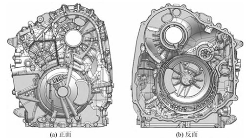
Currently, the mainstream 8AT transmission uses 4 sets of planetary gears and There are 5 shift mechanisms, while the 9AT transmission is equipped with 9 gears to achieve There are 4 sets of planetary gears and 6 sets of shifting mechanisms, and some of them are The optimization and structural topology design of the transmission case, with an overall volume When the outer dimensions are approximately 470 mm × 400 mm × 400 mm, The mass is about 12.6 kg. The overall structure of the casting is complex and the wall thickness is uneven. The average wall thickness is about 6 mm, with the thinnest wall thickness of about 4 mm and the thickest wall thickness of It is about 30 mm, and there are many reinforcing ribs and oil pipes inside, die-casting Stress concentration is likely to occur during the process, resulting in deformation, porosity, and shrinkage of the casting and shrinkage problems. The picture shows the three-dimensional mold of the transmission main housing casting Type diagram.
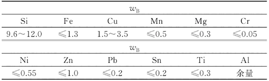
The transmission housing is a part that supports the transmission gear bearing, It is necessary to ensure that the gear can absorb the work under various complex working conditions. force and torque generated during rotation, without deformation or displacement, The precise relative position. This requires the main housing to have high strength The density and stiffness of ADC12 die-casting aluminum alloy are lower than those of traditional materials, but the specific strength With the characteristics of high rigidity and high strength, it can meet the production requirements of the main shell. The table shows its chemical composition.
design of gating system
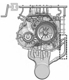
The design scheme of the pouring system is shown in Figure 2. The shape of the main transmission housing is irregular. Then, the depth of the internal cavity varies. The internal gate of this casting is located in the deep cavity. on the left side, which is beneficial for filling the deep cavity, and on the right side valve plate surface, The branch (dashed line) is beneficial for the shape of the complex valve plate surface Fill the mold.
Determination of process parameters
Based on the design manual of die casting process and practical production experience, the working procedures and technical parameters are preliminarily determined. Technical parameters: the initial temperature of the metal liquid is 680℃, and the initial temperature of the mold is 200 ℃, total mass of about 18.95 kg, total projected area of 265 327 mm2; The injection pressure is selected as 80 MPa, and the safety factor is selected as 1.2. Through calculation, the clamping force is approximately 25,470 kN, so the Bühler type is selected. CATAT305 die casting machine, clamping force of 30 500 kN, punch The diameter is ϕ150 mm, the low-speed injection speed is 0.2 m/s, and the high-speed injection speed is The speed is 3.5 m/s, and the total length of the material cylinder is 800 mm.
The usual die casting production process generally takes the metal liquid to the ingate The position of the is the high-low speed switching point, but due to the complex shape of the main housing, it is The box structure does not apply to the conventional high and low speed switching points. Combined with the early stage For work and a large number of simulations, the high-low speed switching point is taken as 480 mm for molten metal When reaching the position of the gate, the high-low speed switch point is taken as 520 mm for metal The liquid branches from the middle 5 paths into the cavity and smoothly meets at the high and low speed positions When the switching point is taken as 560 mm, it is the metal liquid in the cavity and the right branch metal. The position where the liquid and material smoothly intersect. Therefore, in order to study the high and low speed cutting of injection molding, To investigate the influence of the change point on the filling process of the transmission main housing, design three simulation scenarios with high and low speed switching points set at 480, 520, and 560 mm, respectively Don’t just plan on option 1, option 2, and option 3.
Simulation Results and Analysis
In order to understand the filling situation during the die casting process of the transmission main housing, Numerical simulation was performed using Flow-3D software. Figure 3 shows the filling process of scheme 1 process. It can be seen that due to the uneven flow of the molten metal into the mold cavity, Instead of filling the cavity directly at high speed, a The very obvious jet flow (dashed box in Figure 3b) is very likely to produce backflow and air entrainment. There is a clear unfilled part at the arrowhead of the shallow cavity on the left side, which will be filled in the future. The gas escaping from the cavity is enveloped by the molten metal, causing the transmission main housing Internal porosity defects occur. The left side of the cavity fills slowly, causing gas Serious, it has a great impact on the quality of die-casting parts.
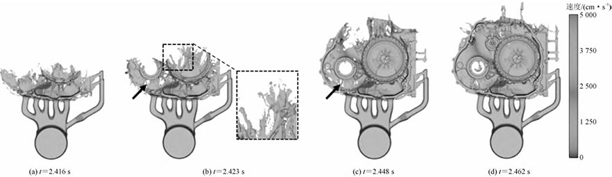
Figure 4 shows the filling process of Scheme 2. It can be seen that due to the high viscosity of the molten metal, Smooth intersection, when the injection speed is converted from low speed to high speed, the metal liquid can The filling is stable enough. Compared with Scheme 1, the front jet flow has been significantly improved, with The side airflow phenomenon has also been significantly improved. However, due to the left side For shallow cavity areas, less metal liquid is required to be filled, and after the metal liquid smoothly meets When the high-speed injection starts, the molten metal first enters the shallow cavity on the left side, forming a small A small amount of gas is trapped in the metal liquid in the shallow cavity on the left side (see the arrow in Figure 4b). at the head).
Figure 5 shows the filling process of scheme 3. From Figure 5a, it can be seen that in When the high and low speed switching points are switched, the molten metal has already been separated from the right side. When the injection speed is switched from low to high, the metal liquid is smoothly merged. Due to the filling effect of the right branch on the right deep cavity, the molten metal can The left shallow cavity area and the right deep cavity area can be filled simultaneously, and the molten metal flows The filling is carried out in a laminar flow manner. The jet flow generated during the entire filling process is very Small, and the filling is relatively uniform, with no gas encapsulation in the shallow cavity on the left side The smooth filling process is beneficial for discharging the gas inside the cavity, thereby reducing the occurrence of porosity defects.
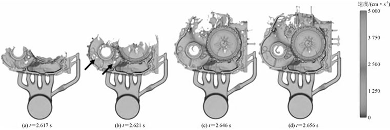
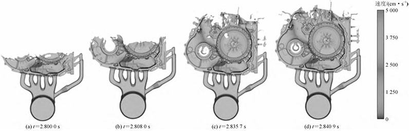
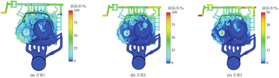
Figure 6 shows the probability model of air entrapment in each part after filling the mold with three different schemes The results show that the injection high-low speed switching point has a significant impact on the filling process of die casting. When the high and low speed switching point of injection is too early, the metal liquid will The injection creates a jet, causing a large amount of splashes, which increases the porosity defects. Increase the low-speed injection stroke and appropriately postpone the high-low speed switch The point can make the molten metal flow smoothly into the cavity and evenly dispersed. When When the low-pressure injection speed is converted to high-pressure injection speed, the force brought by the punch is uniform dispersed in various parts of the molten metal, rather than concentrated in one location, thus improving the flow during filling. According to the simulation results, When the high-low speed switching point is 480 mm, the left shallow cavity and the end The probability of end-rolling gas is about 30%, and a small part reaches 50%; when the high and low speed switching point When the diameter is 520 mm, the left shallow cavity area is significantly improved, only the distal part The probability of air separation reaches 50% when the high and low speed switching point is 560 mm The overall probability of air entrapment is the smallest, and the probability of air entrapment in the shallow cavity area on the left side is lower than 13%, and the probability of air-entanglement in the end part is less than 30%. Compared to the square The overall filling process of Case 1, Case 2, and Case 3 is the most stable, with the generation of air entrapment The probability is the smallest.
Microstructure and mechanical properties
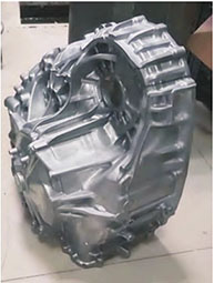
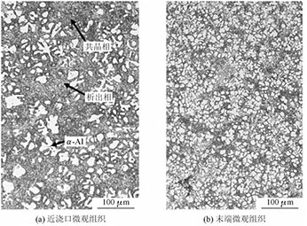
The parameters of scheme 3 were used for actual production, and the outline was obtained Clear and high-precision transmission main housing castings, as shown in Figure 7. As can be seen, the casting surface is smooth, without porosity and oxidation inclusions. Samples were taken from the near-gate position and the end position for microscopic observation and force testing. Figure 8 shows the microstructure of the main housing of the 9AT transmission. As shown in Figure 8a, the shell structure is mainly composed of α-Al and α-Al+Si co-grains. Crystal phase composition, part of the primary α-Al phase presents dendritic morphology, and part The eutectic Si exists in the form of needle-like and flake-like. At the same time, the matrix There are a small amount of massive precipitates in the body. From Figure 8b, it can be seen that due to the end cold However, the growth rate is faster, and the initial α-Al and eutectic Si cannot continue to grow. A large amount of initial The α-Al grains are spherical in shape. It can be seen that the microstructure of the main shell of 9AT is relatively
Conclusion
(1) During the mold filling simulation, it was found that the high-low speed switching point was 560 mm. The entire filling process is stable and uniform, compared to the high and low speed switching points. The probability of generating air entrapment is the lowest at 480 and 520 mm. (2) Select the injection low-speed value of 0.2 m/s and high-speed value of 3.5 m/s, The high-low speed switching point is 560 mm for actual production trial production, and the trial production of variable speed system The appearance of the main housing of the speed reducer has no obvious defects, and the internal grain structure is fine and distributed Uniform and dense organization. The tensile strength and elongation near the gate are 272.0 MPa, 3.4%, and the tensile strength and elongation at the end are 230.6 MPa, 2.7%, which meets the mechanical performance requirements of the transmission main housing.