
In modern manufacturing, lost foam casting has emerged as a highly competitive advanced casting process due to its advantages of high dimensional accuracy, smooth surface finish, and reduced environmental pollution compared to traditional sand casting methods. This process involves placing a polystyrene foam pattern coated with refractory material into a flask, filling it with unbonded dry sand, and maintaining a specific negative pressure during pouring and solidification to ensure sand strength and proper gas evacuation. The high-temperature metal causes the foam to decompose and “disappear,” while negative pressure facilitates the removal of gaseous by-products, allowing the metal to fill the cavity and form the casting. Key factors influencing vacuum negative pressure lost foam casting include vibration parameters of the compaction table, gating system design, molding scheme (burial method), carbon equivalent, negative pressure level, and pouring temperature.
Gearbox housings for automobiles, agricultural machinery, and engineering vehicles are typically produced in large batches, feature complex structures, and require lightweight designs. Traditional sand casting often leads to issues like uneven wall thickness, excessive flash, and sand inclusions, making lost foam casting a more suitable alternative. These castings must undergo pressure leakage tests, demanding dense internal structures free from slag inclusions and internal porosity. In this study, we optimize the lost foam casting process for three types of thin-wall gray iron gearbox housings using orthogonal experiments focused on gating system design, burial scheme, carbon equivalent, negative pressure, and pouring temperature to achieve high-quality castings.
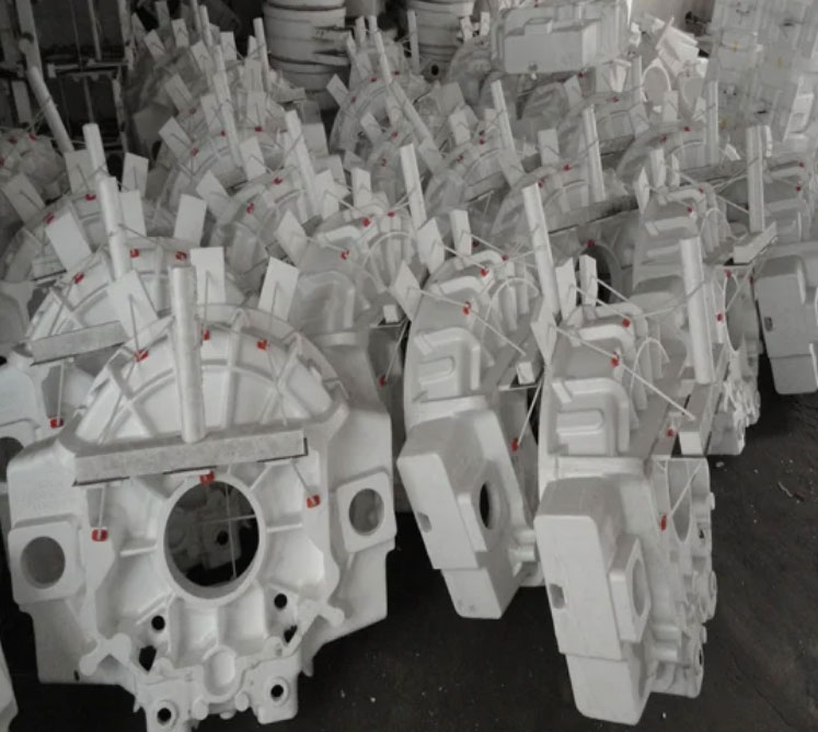
Our production conditions included specific parameters: raw sand with a primary mesh size of 20–40目 (85% or more) and mud content ≤0.3%; coating thickness of 1.0–1.5 mm and moisture content ≤1%; flask dimensions of 2050 mm × 1500 mm × 1300 mm with five-sided ventilation and a bottom vacuum source, utilizing 70 flasks in a vacuum negative pressure production line; and an automatic teapot pouring machine with a maximum single-batch pouring mass of 2100 kg. The three gearbox housings studied—designated as A, B, and C—were used in large agricultural machinery, with details summarized in Table 1. All shared characteristics of thin walls (5–7 mm) and required 3 kg hydraulic pressure leakage testing. Due to large flask sizes, cluster casting with multiple pieces per flask was adopted for efficiency, posing significant production challenges.
| Product | Material | Dimensions (mm) | Wall Thickness (mm) | Weight (kg) |
|---|---|---|---|---|
| Housing A | HT300 | 780 × 450 × 440 | 5–6 | 100 |
| Housing B | HT300 | 680 × 320 × 245 | 6–7 | 100 |
| Housing C | HT300 | 440 × 420 × 380 | 5–6 | 68 |
Initial production runs revealed major quality issues, including high failure rates in hydraulic leakage tests and visible defects such as slag inclusions and cold shuts. For instance, Housing A exhibited leakage points concentrated in specific areas, while slag and cold shut defects were prevalent across samples. These problems necessitated a comprehensive optimization of the lost foam casting process, starting with the gating system and burial scheme.
In the initial gating system design, we employed a combination of bottom and middle pouring with stair-step configurations. For Housing A, a star-shaped gating system was used with a 50 mm diameter sprue, four 30 mm × 20 mm runners, and eight 40 mm × 10 mm ingates, resulting in a sprue-runner-ingate area ratio of 1:1.3:1.7. Housing B featured a single-side stair-step system with a 50 mm sprue, four 30 mm × 20 mm runners, and six 30 mm × 15 mm ingates, giving an area ratio of 1:1.3:1.4. Burial involved positioning non-pressure-bearing areas downward, with six pieces per flask. However, this led to inadequate filling and defects, prompting a redesign focused on open gating systems with multi-point entry and faster pouring to minimize filling time. The optimized designs, detailed in Table 2, incorporated double pouring gates and three-layer stair-step configurations to enhance metal distribution and reduce turbulence.
| Product | Sprue (mm) | Runner (mm) | Ingate (mm) | Number of Ingates | Area Ratio (Sprue:Runner:Ingate) |
|---|---|---|---|---|---|
| Housing A | Ø70 | 35 × 20 | 50 × 10 | 12 | 1:1.1:1.5 |
| Housing B | Ø70 | 40 × 20 | 50 × 15 | 7 | 1:1.2:1.4 |
| Housing C | Ø50 | 30 × 20 | 40 × 10 | 6 | 1:1.3:1.3 |
The burial scheme was also revised to position pressure-bearing areas downward, improving solidification and reducing leakage risks. For example, Housing A was buried with the大口 upward (pressure-bearing side down) in clusters of eight pieces per flask, while Housing B and C adopted similar orientations. This adjustment, combined with the optimized gating, significantly enhanced casting integrity in lost foam casting applications.
Negative pressure is a critical factor in vacuum lost foam casting, as it affects dimensional stability, mold collapse, slag defects, and sand adhesion. To determine the optimal negative pressure for thin-wall castings, we conducted experiments on Housing A using the improved gating system and a pouring temperature of 1470°C. Negative pressure was incrementally increased from 0.04 to 0.052, with each 0.001 step tested on two flasks (16 castings). Results, summarized in Table 3, showed that higher negative pressure reduced leakage and slag defects up to a point, with 0.049 providing the best outcomes. However, negative pressure alone was insufficient to eliminate defects entirely, indicating the need for further parameter adjustments.
| Negative Pressure | Leakage Rate (%) | Slag Defect Rate (%) |
|---|---|---|
| 0.040 | 45 | 40 |
| 0.045 | 38 | 35 |
| 0.049 | 25 | 22 |
| 0.052 | 28 | 26 |
Pouring temperature plays a vital role in ensuring complete filling and minimizing cold shuts in lost foam casting. Initially set at 1470°C based on similar castings, this resulted in cold shut defects. We systematically increased the temperature for Housing A, using the optimized gating and a carbon equivalent of 3.8%, with tests at 5°C increments (two flasks per step). As shown in Table 4, higher temperatures reduced leakage and slag defects, with cold shuts eliminated above 1500°C and optimal results achieved at 1520°C. The relationship between pouring temperature (T) and defect rate (D) can be approximated by a linear model: $$D = a – bT$$ where a and b are constants derived from experimental data, indicating that increasing temperature improves fluidity and reduces defects in lost foam casting.
| Pouring Temperature (°C) | Leakage Rate (%) | Slag Defect Rate (%) | Cold Shut Incidence |
|---|---|---|---|
| 1470 | 40 | 38 | High |
| 1490 | 32 | 30 | Moderate |
| 1510 | 20 | 18 | Low |
| 1520 | 15 | 14 | None |
Carbon equivalent (CE) is another key parameter influencing the microstructure and soundness of gray iron castings in lost foam casting. We evaluated Housing A at a pouring temperature of 1515–1525°C, varying CE from 3.6% to 4.3% in 0.1% increments (two flasks per step). The carbon equivalent was calculated using the formula: $$CE = C + \frac{Si}{3}$$ where C and Si are the percentages of carbon and silicon, respectively. For instance, a CE of 4.1% corresponds to C=3.5% and Si=1.8%. Results in Table 5 demonstrate that higher CE values reduced leakage and slag defects, with CE=4.1% yielding the best performance. Beyond 4.2%, improvements plateaued, suggesting an optimal range for thin-wall castings in lost foam casting.
| Carbon Equivalent (%) | Leakage Rate (%) | Slag Defect Rate (%) |
|---|---|---|
| 3.6 | 35 | 33 |
| 3.8 | 28 | 26 |
| 4.1 | 12 | 10 |
| 4.3 | 13 | 11 |
Integrating these optimizations, we derived a comprehensive model for the lost foam casting process. The overall defect rate (D_total) can be expressed as a function of key variables: $$D_{\text{total}} = f(P, T, CE, G)$$ where P is negative pressure, T is pouring temperature, CE is carbon equivalent, and G represents gating design parameters. Empirical data from our experiments allowed us to refine this model, showing that synergistic adjustments yield the best results. For example, the interaction between pouring temperature and carbon equivalent can be described by: $$D_{\text{leakage}} = k_1 – k_2 \cdot T – k_3 \cdot CE$$ where k1, k2, and k3 are coefficients specific to the lost foam casting setup.
In conclusion, our optimization of the lost foam casting process for thin-wall gray iron gearbox housings demonstrates that high-quality castings can be achieved by controlling key parameters: pouring temperature above 1510°C, carbon equivalent of 4.1%, negative pressure of 0.049, and a burial scheme with pressure-bearing areas downward. The use of open gating systems, double pouring gates, and three-layer stair-step multi-point entry ensures rapid and uniform filling. This approach not only addresses common defects like leakage and slag but also enhances the efficiency and reliability of lost foam casting for complex, thin-wall components. Future work could explore dynamic modeling of foam decomposition and metal flow to further refine the process, solidifying the position of lost foam casting as a leading method in advanced manufacturing.