
1. Product structure and technical requirements
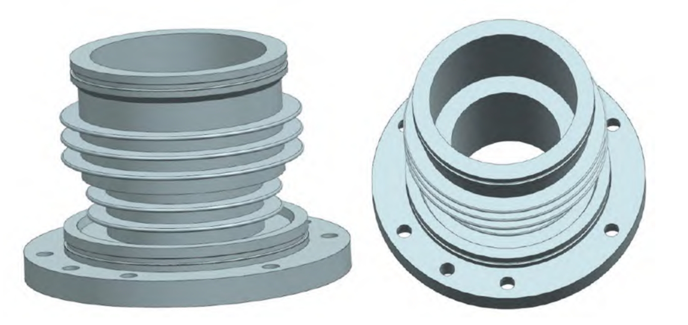
The bearing liner plays a crucial role in reducing wear, supporting operation, vibration reduction, and heat dissipation in bearings, and is crucial for the normal and long-term use of bearings. Figure 1 shows a schematic diagram of a sand casting manufacturer developing a lining steel casting for bearings, with a weight of approximately 14 kg and a material of ZG15Cr12. The chemical composition is shown in Table 1, and the mechanical properties are shown in Table 2. The contour dimensions of the casting φ 240 mm x 165 mm, with a maximum wall thickness of 32 mm and a minimum wall thickness of only 4 mm. The manufacturer of sand castings has developed a bearing liner steel casting requirement that there should be no defects such as shrinkage, porosity, cracks, and cold shuts. After processing, a 15 minute static water pressure test should be conducted for 10 minutes, and there should be no leakage, leakage, sweating, or other phenomena.
| C | Si | Mn | P | S | Cr | Ni |
| ≤0.15 | ≤0.8 | ≤1.0 | ≤0.035 | ≤0.025 | 11.5~13.5 | ≤0.6 |
| Rm /MPa | ReL /MPa | A/% | Z /% |
| ≥590 | ≥390 | ≥25 | ≥55 |
Sand casting manufacturer develop bearing liner steel castings with relatively simple overall structures due to their small single weight. However, sand casting manufacturer develop bearing liner steel castings with 5 circular heat dissipation ribs on the outer side, with a thickness of only 4 mm and a height of 14 mm. Through structural analysis of bearing liner steel castings, there are several casting difficulties as follows:
1) Sand casting manufacturer develop bearing liner steel castings with extremely small heat dissipation rib plate thickness, poor fluidity of steel liquid, and difficulty in fully filling the mold, which easily leads to cold shut defects. In sand casting, when the size of low alloy steel castings is between 200 mm and 400 mm, the minimum wall thickness of bearing liner steel castings developed by sand casting manufacturer should not be less than 9 mm. However, the wall thickness of this bearing liner steel casting is only 4 mm, which far exceeds the limit of traditional sand casting. Therefore, the thin-walled rib plate forming of this bearing liner steel casting is the biggest difficulty in bearing liner steel casting.
2) In order to ensure the forming problem of the rib plate of the bearing liner steel castings developed by sand casting manufacturer, the pouring temperature of the bearing liner steel castings needs to be relatively increased. The use of a 1.5 ton ladle and a smaller product weight in ZHY Casting’s actual production will make it difficult to control parameters such as pouring temperature and pouring time, becoming a major factor affecting the forming of the bearing liner steel castings.
2. Casting process design
2.1 Selection of pouring position
Considering the problems of thin rib plates, difficult forming, and high difficulty in demolding of bearing liner steel castings developed by sand casting manufacturer, sand 3D printing technology is adopted for production to improve operability and reduce research and development costs. 3D printing sand mold is a core produced using 3D printing technology, which uses a 3D printer to process and stack any shape of the cavity layer by layer. Materials can be added layer by layer to produce 3D solids. 3D printing is not limited by shape, except for closed holes, more complex products are more suitable for 3D printing production. The use of sand mold 3D printing technology for production does not require consideration of molding issues. Sand mold casting manufacturers do not need to increase the draft angle on bearing liner steel castings, resulting in higher dimensional accuracy and more flexible design.
Based on the analysis of casting difficulties and the advantages of sand mold 3D printing technology, a process plan of one mold with multiple parts and vertical pouring is selected. The specific pouring position is shown in Figure 2. Placing the pouring position here has the following advantages:
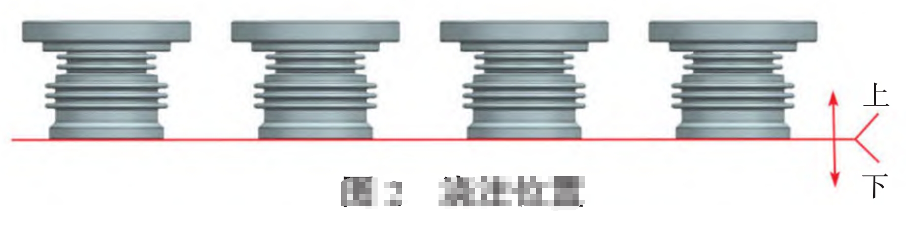
1) The design of the bottom pouring system is conducive to smoothly filling the mold cavity, reducing sand flushing on the core, reducing turbulence, and facilitating gas discharge;
2) The use of vertical pouring is beneficial for the overall shrinkage of castings and facilitates the placement of shrinkage risers;
3) One type multiple parts increase the weight of single box pouring, improve production efficiency, and improve the controllability of pouring temperature.
2.2 Riser and cold iron design
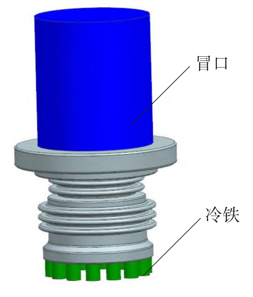
For sand casting manufacturer developing bearing liner steel castings, the fluidity of the steel liquid is poor and the feeding efficiency is far lower than that of cast iron products. In order to ensure that sand casting manufacturer obtain sufficient feeding liquid for bearing liner steel castings, it is necessary to ensure that the feeding liquid amount of the riser is greater than one-third of the weight of the position being fed and the weight of the hidden riser. At the same time, it is necessary to ensure that the modulus of the riser is greater than or equal to 1.2 times the modulus of the casting, And it is necessary to ensure the smoothness of the entire solidification process and the feeding and shrinking channels cannot be interrupted in advance. By using CAE simulation software to analyze the distribution of hot spots in the product, determine the size of the casting modulus, and use one top riser to provide shrinkage. The size of the riser is determined by the casting modulus and the amount of shrinkage liquid. By providing subsidies and cold iron, we ensure smooth filling and contraction channels, obtain products without shrinkage holes or porosity defects, and ensure the quality of bearing liner steel castings. Figure 3 shows the riser and cold iron design of the bearing liner.
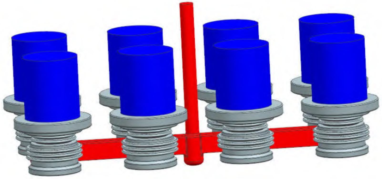
2.3 Pouring System Design
The sand casting manufacturer has developed bearing liner steel castings with small unit weight, simple structure, and relatively uniform wall thickness except for the rib plate. Considering the difficulty in forming the rib plate, the pouring system adopts an open bottom pouring system, with a ratio of 1:2:5 for the cross-sectional area of the sprue, transverse sprue, and inner sprue This pouring system ensures that the temperature difference between the upper and lower cavities of the metal liquid is not large, and the metal liquid enters uniformly and steadily, reducing the turbulence of the metal liquid and facilitating gas discharge. At the same time, the impact force on the core is small, avoiding sand flushing. Figure 4 shows the design of the pouring system for the bearing liner.
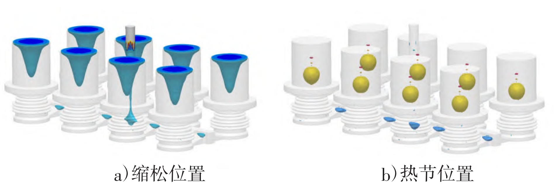
2.4 CAE simulation
The development of CAE simulation technology plays an important role in the development of the casting industry. Through CAE simulation, various defects caused by casting process design can be avoided as much as possible, reducing the cost of research and development of bearing liner steel castings, reducing design costs, and shortening the design cycle. Table 3 shows the simulation parameters of bearing liner steel castings developed by sand casting manufacturer.
| Material quality | Pouring weight/kg | Pouring temperature/℃ | Filling time/s |
| ZG15Cr12 | 500 | 1 600±5 | 27 |
Using CAE simulation software, conduct a three-dimensional simulation of the casting process. By analyzing the simulation results, adjust and optimize the riser, cold iron, and subsidies of the casting process, and obtain the optimal process plan. The final CAE simulation results show that the entire solidification process meets the requirements of sequential solidification, the riser and cold iron settings are relatively reasonable, and the sand casting manufacturer has developed bearing liner steel castings with no tendency for shrinkage and looseness. Simulate the filling process of the process plan, simulate the pouring process, and the simulation results show that the pouring system is designed reasonably, the metal liquid rises steadily in the mold cavity without splashing, and there is no entrainment during the entire pouring process. Figure 5 shows the porosity and hot spot diagram of the CAE simulation analysis of bearing liner steel castings developed by sand casting manufacturer. From the porosity chart, it can be seen that there is no shrinkage porosity in the casting body, and the shrinkage porosity is concentrated between the riser and the runner, and there is a certain distance from the casting body, indicating that the feeding shrinkage effect of the riser is good. From the hot spot diagram, it can be seen that there are no large hot spots on the casting body, and the hot spots are concentrated in the riser, indicating that the size of the riser is appropriate and there is no risk of root shrinkage.
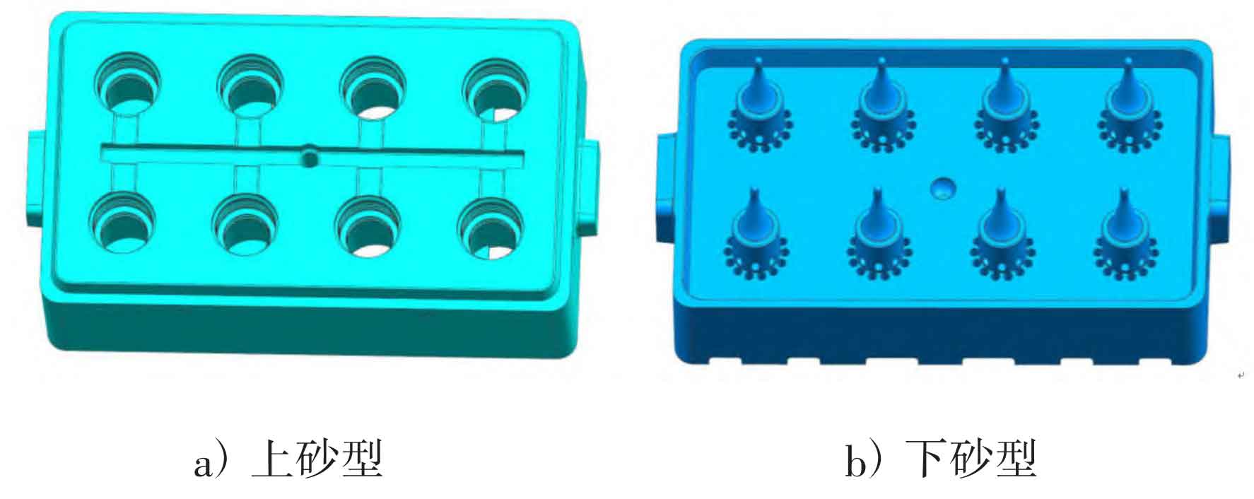
2.5 3D printing sand mold design
The sand casting manufacturer has developed bearing liner steel castings with relatively thin rib plates. Considering the characteristics of 3D printed sand molds, the bearing liner steel castings developed by the sand casting manufacturer are divided into two sand molds on the lower flange surface. The entire reinforcement plate and pouring system are in the same sand mold, and the overall size is more guaranteed. There will be no significant size deviation due to the assembly of the core and box, and the seam is also very small, greatly reducing the workload of subsequent cleaning. The cold iron of the 3D printed sand mold is directly formed by reserving corresponding holes on the sand mold, which has precise control over the position and provides a great guarantee for the quality of the bearing liner cast steel parts. Figure 6 shows the sand mold diagram of a bearing liner steel casting developed by a sand casting manufacturer, including upper and lower sand molds.
2.6 Melting and pouring
Melting is carried out using an intermediate frequency induction furnace, and production is carried out by blowing argon for degassing and deoxidating aluminum particles. During the production process, it is necessary to ensure the pouring temperature and pay attention to controlling the temperature drop to ensure that there are no cold shut defects during the pouring process of bearing liner steel castings developed by sand casting manufacturer. To bake the ladle, ensure that the baking temperature is above 900 ℃. The water outlet temperature is 1660 ℃± 5 ℃, and the pouring temperature is 1595 ℃± 5 ℃ for pouring.
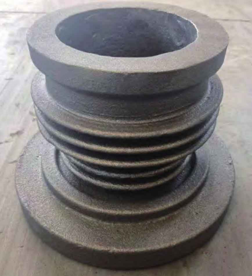
3. Production validation
The bearing liner castings produced by sand casting manufacturer are shown in Figure 7 after removing shot blasting from the pouring system. It can be seen that the sand casting manufacturer has developed a bearing liner steel casting that is integrally formed, with good appearance quality and uniform wall thickness. After inspection, the sand mold casting manufacturer has developed bearing liner steel castings that meet customer inspection requirements, and the composition and performance also meet customer specifications. It has achieved stable mass production using sand mold 3D printing technology.
4. Conclusion
Sand casting manufacturer analyze the casting difficulties of bearing liner products and combine CAE three-dimensional simulation technology to optimize and improve each part from pouring position, pouring system, cold iron design, sand mold design, and smelting and pouring. With the cooperation of sand mold 3D printing technology, the entire production process of bearing liner steel castings developed by sand mold casting manufacturers is simpler, eliminating the steps of mold making and manual core making, greatly shortening the development cycle of bearing liner steel castings by sand mold casting manufacturers. At the same time, the 3D printing sand mold process reduces the number of gaps in the bearing liner steel castings, makes the pouring system design more flexible, reduces the workload of subsequent cleaning, reduces production costs, improves production efficiency, and ensures the quality of bearing liner steel castings developed by sand mold casting manufacturers.