
0 Introduction
In the production process of complex castings, due to many production parameters and complex production environment, various defects often occur in castings. Numerical simulation of the casting process of castings and optimization of casting process scheme can reduce the production cost of castings and enhance the competitiveness of foundry enterprises. Current Foundry CAE The software is generally able to simulate the casting filling process, solidification process, microstructure, stress and strain and heat treatment process. Huazhu CAE/InteCAST numerical simulation software is an integrated software system for solidification simulation of castings developed by Huazhong University of Science and Technology, which is composed of three relatively independent modules: pre-processing part, calculation processing part and post-processing part, and is the leader in domestic foundry CAE software. In 2015, Huazhu CAE numerical simulation software was used to simulate the centrifugal casting filling and solidification process of a titanium alloy thin-walled part, predicted the location of defects, and increased the centrifugal force by increasing the rotation speed, enhancing the ability of molten metal to fill the cavity, effectively reducing the shrinkage porosity volume and improving the defects. In 2020, the influencing factors of mold strength were introduced by using the shrinkage modulus method, a numerical simulation scheme of complex ductile iron castings was designed, Huazhu CAE was used to simulate, the simulation data were analyzed, and the riser of ductile iron castings was designed according to the influencing factors of mold strength. In 2014, Huazhu CAE was used to simulate the filling and solidification process of aluminum alloy impeller castings, analyze shrinkage porosity and shrinkage porosity defects, obtain a better process scheme, and carry out actual pouring verification. In 2012, in order to dig deeper into the production mechanism of vertical centrifugal casting, Huazhu CAE was used to carry out numerical simulation research on the filling and solidification process of titanium alloy vertical centrifugal casting, and a simulation and analysis system for the filling and heat transfer process of Chin alloy vertical centrifugal casting was developed. In 2013, the total solidification time of the ram casting and the formation process of the porosity were numerically simulated, and the simulation results showed that the total solidification time of the casting could be shortened and the tendency of the ram casting to produce porosity could be reduced when the pouring temperature was reduced and the cold iron was set at the bottom of the casting. In 2010, numerical simulation was used to calculate the solidification process of ductile iron shell castings, and based on the liquid phase distribution obtained by simulation, the design of the casting tooling of the casting was completed through trial production, which laid the foundation for actual production. In 2019, numerical simulation analysis was carried out, and the gating system was modified according to the simulation results, and the new pouring scheme effectively improved the yield of a small ductile iron casting and reduced the tendency of sand inclusion defects. In 2014, Huazhu CAE software was used to simulate the filling and solidification process of ductile iron bridge box casting process, and according to the simulation results, the filling and solidification process was optimized The process scheme of castings reduces shrinkage defects and improves the quality of castings and the yield of processes.
1 Introduction to castings
1.1 Casting application background
The steering axle casting of construction machinery is the key transmission device in the construction machinery vehicle, the physical diagram of the steering axle casting is shown in Figure 1, its material is ductile iron QT450-10, and the alloy composition of QT450-10 is shown in Table 1. Steering axle castings utilize the steering knuckle in the axle to enable the rotation of the vehicle Toward. In addition to vertical loads, steering axle castings are also subjected to longitudinal and lateral forces and the moments resulting from these forces. Therefore, in the process of service, the steering axle casting needs to bear a large load and fatigue effect, and has extremely high requirements for mechanical properties such as strength and fatigue resistance.

Fig.1 Physical drawing of steering bridge casting
1.2 3D model of casting
The 3D model of the steering axle casting is shown in Figure 2. Steering axle castings are in production, and the production method is two pieces in one box. The steering axle casting is changed from the original welded structural parts to the overall formation of ductile iron castings, with many curved surfaces, many mud cores and dispersed, many local thick walls, and scattered hot joints, which leads to its production process Defects such as shrinkage porosity and shrinkage porosity seriously affect the reliability of the manufacturing, assembly and service of steering axle castings.
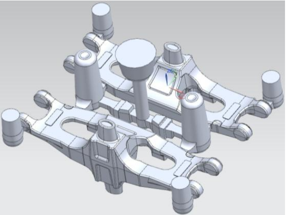
Fig.2 3D model of steering bridge castings
1.3 Casting forming process
The research object of the project is the casting of the steering axle of construction machinery, which is produced by sand casting. Sand casting refers to the casting method of producing castings in a sand mold. Steel, iron and most non-ferrous alloy castings can be produced by sand casting. Due to the low cost of molding materials used in sand casting, the manufacturing of casting molds is simple
It is easy to adapt to a variety of production forms such as single-piece production, small batch production and mass production, and is the basic process in casting production. The basic flow chart of sand casting is shown in Figure 3.
1.4 Main defects of castings
In the actual production process of the steering axle castings studied in the project, the defects are mainly shrinkage porosity and shrinkage porosity. In the solidification process of molten metal, the final solidified part cannot be supplemented by liquid metal, resulting in porosity, in which large and concentrated shrinkage porosity is formed, and small and scattered shrinkage is formed Pine. The dissolved gases in the molten metal or the gases produced by the core remain in the molten metal, and these residual gases cannot escape during the solidification process, thus forming pores. The porosity defect in the steering axle casting is shown in Figure 4.
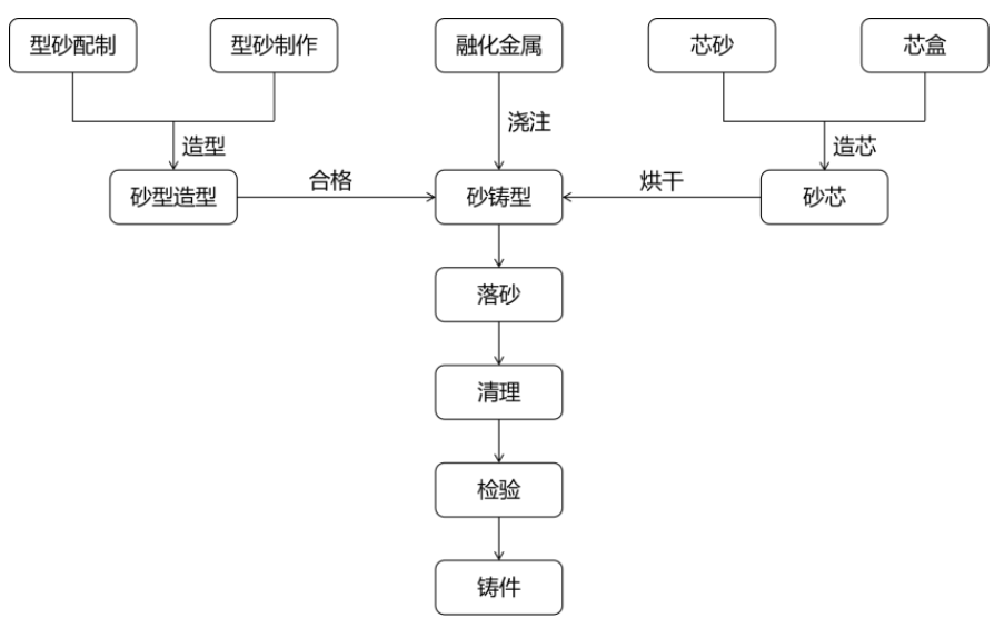
Fig.3 Basic flow chart of sand casting
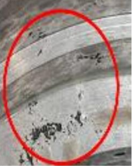
Fig.4 Defect of air hole in steering bridge casting
2 Simulation analysis of single-piece castings
(1) Single-piece simulation scheme (gate riser system): The three-dimensional model of the gate and riser system of the steering axle casting is shown in Figure 5. In the 3D model drawing, the steering axle assembly blank can be divided into two parts: the gate riser system and the casting. There are two main functions of the gate riser: one is to discharge the gas in the cavity and collect the molten metal mixed with inclusions or oxide film at the front of the liquid flow to reduce the defects on the casting; The second is to compensate for the shrinkage of the molten metal during the solidification process to obtain a dense casting without porosity. The pouring mode of the casting is the top column type, and there is a gating inlet in total, and a gate is arranged on the side of the steering axle of a box of two pieces; Due to the complex surface structure of the steering axle casting, the riser is not designed on the surface of the cavity, and the riser is selected to be set on both sides of the cross-sprue of the gating system, and the ordinary riser is selected to realize the shrinkage function.

Fig.5 3D model of casting riser system for steering bridge castings
(2) Process parameter selection and orthogonal simulation experimental designIn the single-piece simulation, the key process parameters have a great impact on the quality of the casting, and six typical process parameters in sand casting, including pouring temperature, initial mold temperature, mold density, mold heat capacity, filling time, and sprue radius, were selected to design orthogonal simulation experiments. According to the actual casting process requirements, the pouring temperature range is determined to be 1 370~1 390 °C, the initial temperature range of the casting mold is 10~30 °C, the casting density range is 1.45~1.65 g/cm3, the heat capacity range of the casting mold is 0.21~0.31 cal/(g·°C), the filling time interval is 15~25 s, and the radius range of the sprue is 25~35 mm show.
(3) Meshing scheme
First, the 3D model is meshed, and the schematic diagram of the meshing results is shown in Figure 6. The mesh type used is a homogeneous grid, the mesh size is set to 4 mm, and the total number of meshes is 5 636 172, which can basically meet the requirements of the simulation for the calculation accuracy.
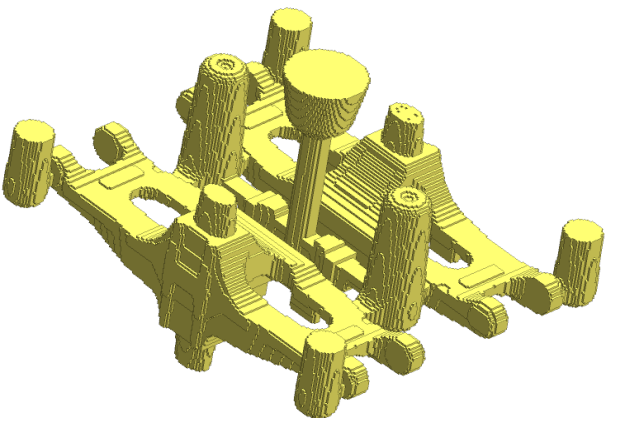
Fig.6 Schematic diagram of grid generation results
2.2 Single-piece simulation results
(1) Simulation results of the filling process
First, the filling process is simulated, and the schematic diagram of the volume filling process is shown in Figure 7. The simulation results show that the molten metal flows into the cross-sprue along the sprue, and the molten metal rushes into the steering axle mold shells on both sides almost synchronously in the cross-sprue, so that the castings of two pieces in one box can be solidified at the same time, so as to reduce the shrinkage porosity caused by the internal cold barrier.

Fig.7 Filling process volume filling diagram
(2) Simulation results of solidification process
Secondly, the solidification heat transfer process is simulated, and the schematic diagram of the temperature change of the solidification process is shown in Figure 8. It can be seen from the temperature change diagram of the solidification process that the solidification process of the casting is generally uniform, and the first solidification part is on both sides of the steering bridge. From the temperature distribution, it can be seen that the solidification process of the casting is complete
The body temperature gradient is gentle, which avoids casting defects caused by rapid cooling.

Fig.8 Schematic diagram of temperature variation during solidification
(3) Residual liquid phase simulation results
Then, the residual liquid phase change process was simulated, and the schematic diagram of the residual liquid phase distribution during the solidification process is shown in Figure 9. Analyzing the simulation results of the residual liquid phase, after solidification at the riser site, there is still an isolated liquid phase area in the middle of the casting that has not yet solidified, so it is possible to target the location of the casting defect Prediction: In the middle of the final solidification of the casting, shrinkage porosity and shrinkage porosity defects may occur.


Fig.9 Schematic diagram of residual liquid phase distribution during solidification
(4) Simulation results of the evolution process of shrinkage porosity defectsFinally, the evolution process of shrinkage porosity is simulated, and the schematic diagram of the evolution process of porosity defects in the solidification process is shown in Figure 10. As can be seen from Figure 10, the porosity and porosity produced by the casting at the final solidification part are basically the same as predicted when the pouring system is designed, and the riser has a certain amount of work for the casting Yes, but it can still be improved for the process design scheme to further reduce the occurrence of shrinkage porosity and shrinkage porosity.

Fig.10 Schematic diagram of evolution process of porosity defect during solidification


Fig.11 The distribution of shrinkage cavity and porosity of 18 groups of simulation results in simulation experiment
2.3 Analysis of single-piece simulation results
(1) According to the results of orthogonal experiments, the total number and volume of shrinkage porosity in 18 groups of orthogonal simulation experiments were counted, and the number and volume of shrinkage porosity and porosity changed with the process parameters as shown in Table 3. As can be seen from Table 3, the groups with a total number of less than 200 porosity are numbered as 5, 7, 10, 13, 14, and 18, and the groups with a total porosity volume of less than 55 cc are numbered 2, 3, and 5, combined with the total number of porosity and porosity The simulation results show that the optimal group number is 5, and its process parameters are 1370 °C, initial mold temperature 30 °C, mold density 1.55 g/cm3, mold heat capacity 0.31 cal/(g·°C), filling time 20 s, and sprue radius 25 mm.
(2) Sensitivity analysis of typical defects to key process parameters
(1) Sensitivity analysis of the influence of pouring temperature on casting defects The schematic diagram of the sensitivity of pouring temperature to the number of shrinkage porosity is shown in Figure 12, and the sensitivity of pouring temperature to the total volume of shrinkage porosity is shown in Figure 13. The number of shrinkage porosities is sensitive to the pouring temperature, and the sensitivity S at the initial temperature of different casting molds is:
S1 (pouring temperature – number of shrinkage porosity) = (a1 + a2 + a3) / 3 = 1.65
S2 (pouring temperature – total volume of shrinkage porosity) (a1+a2+a3)/3=0.2005(2) Sensitivity analysis of the influence of initial mold temperature on casting defects Schematic diagram of the sensitivity of the initial temperature of the mold to the number of shrinkage porosity is shown in Figure 14, the sensitivity of the initial temperature of the mold to the total volume of shrinkage porosity
The schematic diagram is shown in Figure 15. As can be seen from the figure, the number of shrinkage porosities is important for the mold The initial temperature is more sensitive, and the sensitivity S at the initial temperature of different molds is:
S1 (initial temperature of the mold – number of shrinkage porosity) = (a1 + a2 + a3) / 3 = 1.82
S2 (initial temperature of the mould – total volume of shrinkage porosity)
=(a1+a2+a3)/3=0.098
(3) Sensitivity comparison analysis
The analysis shows that the pouring temperature and the initial temperature of the mold have a great influence on the number and total volume of shrinkage porosity. From a quantitative point of view, the sensitivity ratio is about |S1| : |S2| : |S3| : |S4|=1.65 : 0.2005 : 1.82 : 0.098=165 : 20 : 182 : 98。
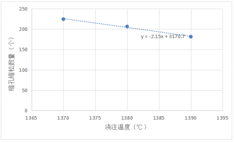
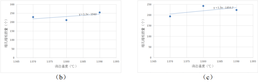
Fig.12 Schematic diagram of sensitivity of pouring temperature to shrinkage cavity and porosity
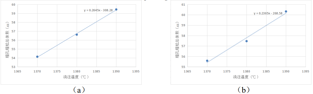
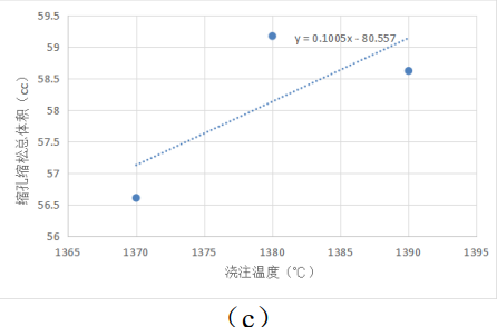
Fig.13 Schematic diagram of the sensitivity of pouring temperature to the total volume of shrinkage cavity and porosity
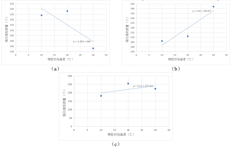
Fig.14 Schematic diagram of sensitivity of initial mold temperature to shrinkage cavity and porosity
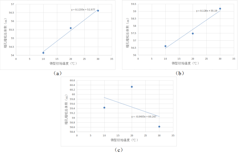
Fig.15 Schematic diagram of sensitivity of initial mold temperature to total volume of shrinkage cavity and porosity
3 Conclusion
For the steering axle castings of construction machinery, the orthogonal simulation experiment scheme was designed by using the CAE numerical simulation software of Huazhu, the filling and solidification process and the formation process of shrinkage porosity were numerically simulated, and the crater shrinkage defects of the castings were quantitatively analyzed by using six typical process parameters, and finally the influence of the key process parameters, the pouring temperature and the initial temperature of the casting mold on the casting defects, and the sensitivity of the two process parameters on the casting defects was analyzed. Finally, the quantitative conclusion of the influence of the two process parameters on the porosity and porosity defects is obtained, which is practical The casting production and process optimization of the company provides precise theoretical guidance.