
Sand casting is a widely used method for producing metal parts, particularly for larger components and those made from materials with a high melting point. The process involves creating a mold from a mixture of sand and a binder, which is then used to shape the molten metal into the desired part. Here are the main steps in the sand casting process:
- Pattern making: A pattern, which is a replica of the final part, is made from wood, plastic, or metal. This pattern includes allowances for shrinkage, machining, and any draft angles required for easy removal from the sand mold.
- Mold preparation: The pattern is placed in a molding box, also known as a flask, which is filled with molding sand. The sand is compacted around the pattern to create an impression of the part. The flask is usually made up of two halves, the cope (top) and drag (bottom).
- Core making (if necessary): If the part has internal cavities or hollow sections, a sand core may be required. The core is made by packing a sand mixture around a core pattern and allowing it to harden. The core is then placed inside the mold cavity before the molten metal is poured.
- Mold assembly: The cope and drag are assembled, with the core (if needed) accurately positioned inside the mold cavity. The mold is then closed, and any necessary vent holes or gating systems are created to facilitate the flow of molten metal and the escape of gases.
- Pouring: The molten metal is heated to the appropriate temperature and carefully poured into the mold through the gating system. The metal fills the cavity, taking the shape of the pattern, and is allowed to cool and solidify.
- Cooling and solidification: As the metal cools, it solidifies and takes the shape of the desired part. This process can take anywhere from a few minutes to several hours, depending on the size and complexity of the part, as well as the material used.
- Mold removal: Once the metal has completely solidified, the sand mold is broken away, and the casting is removed. The sand can be reused for future castings after proper reconditioning.
- Finishing and cleaning: The casting is cleaned to remove any residual sand, and the gating system is cut off. The part may require additional machining, grinding, or finishing to achieve the desired dimensions and surface finish.
Sand casting is a versatile and cost-effective method for producing parts, especially for small to medium production runs or large components. However, it has some limitations in terms of surface finish, dimensional accuracy, and intricacy when compared to other casting methods like investment casting or die casting.
Chapter 1:How to eliminate crack defects in sand casting parts
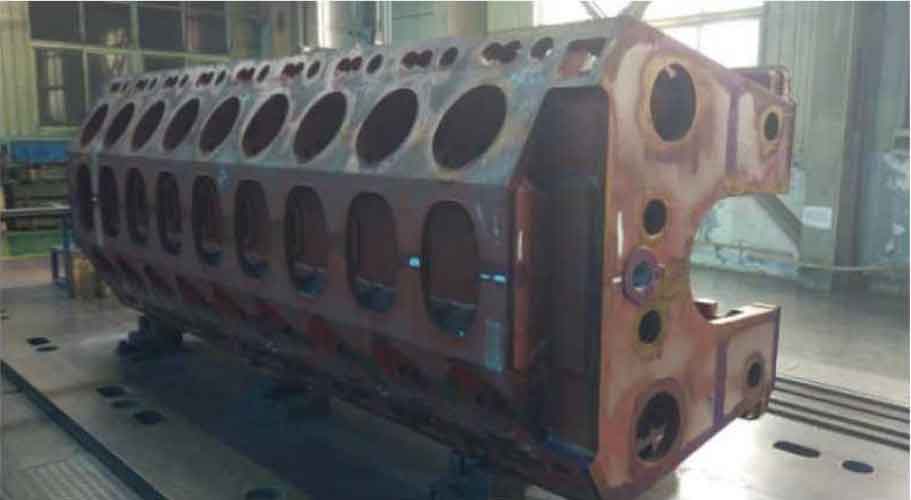
The butterfly valve plate type sand casting is made of ASTM A351 CF8M austenitic stainless steel, with a blank weight of 22 kg per unit, a maximum wall thickness of 45 mm, a minimum wall thickness of 7 mm, and an accurate contour size of 400 mm x 65 mm. The structure and dimensions of the sand casting parts are shown in Figure 1. Water glass self hardening sand molding, hand made core with coated sand hot box, melted in a 2 T electric furnace, and manually lifted and poured. After solid solution treatment, sand casting parts are sent abroad for precision processing and forming, assembled into complete valves, and sold to the European market.

Starting from the end of 2023, the outer diameter of sand castings will be rough machined from a rough rough rough 400 mm to (accurate 396.6+1) mm before shipment. Foreign factories will process butterfly valves according to the required pressure levels of PN6, PN10, and PN16 in the order, and then precision machined to accurate 390.6~accurate 391.6 mm respectively, and undergo mirror polishing treatment. The quality of the sealing surface is related to the sealing performance of the valve body. No sand casting holes or cracks are allowed, and welding repair is also not allowed.
1. Quality issues that arise during the bulk supply phase
As of the end of March 2024, a total of 345 sand casting parts were processed by foreign factories, and 107 were scrapped due to crack defects on the sealing surface, with a scrap rate of about 31%, seriously affecting the efficiency of the machining workshop and customer delivery requirements. The crack defects on the sealing surface after machining are shown in Figure 2, and the right image is a partial enlargement of the left image. The customer attaches great importance to this and requests the sand casting supplier to produce sand casting parts locally at no cost to meet the delivery time requirements of the final customer order. If waste is considered in the sand casting factory, the comprehensive waste rate of the product is close to 40%, and the supplier faces enormous cost pressure.

2. Analysis of the causes of quality issues
In response to customer feedback, 25 inventory sand casting parts were roughened to a precision of 396.6mm and tested for sealing surfaces using PT. The results showed that 7 of them had crack defects, with severe oxidation and tearing on the surface, with a width of about 1mm, penetrating the entire sealing surface. The shape on the right side of Figure 2 is basically similar to the customer feedback, with a defect rate of 28%, which is also close to the customer feedback of 31%. It is preliminarily determined that the hot crack defect is caused by improper control of solid solution treatment, material composition and metallography, and sand casting process.
2.1 Solid solution treatment process tracking
The purpose of solid solution treatment for austenitic stainless steel is to make carbides and σ Fully dissolve at high temperatures and retain in austenite at room temperature, thereby obtaining a single-phase austenite structure at room temperature, giving the steel good mechanical and corrosion resistance properties. The sand casting suppliers that the author has encountered in the actual operation process are prone to problems such as uneven heating of the heat treatment furnace, uncalibrated temperature controllers, uncontrolled placement gaps of sand casting parts, long quenching water inlet time, and uncontrolled water temperature, which can easily cause uneven hardness of sand casting parts after solid solution treatment and difficulties in later processing.
To verify whether the supplier’s solid solution treatment process meets the process requirements, the heat treatment process was witnessed on site. 18 valve plates that have passed the PT inspection are vertically placed inside the heat treatment frame, with a valve plate spacing controlled at about 5 cm. After heating up to 1080 ℃ according to the heat treatment furnace setting program, they are insulated for 2 hours. The quenching water is quickly discharged from the furnace, and the sand casting swings back and forth in the water pool to fully cool before being discharged. The entire solid solution treatment process complies with the process operation regulations formulated by the factory. After heat treatment, the valve plate was turned 1mm on one side and the sealing surface was inspected by PT. No cracks were found. This indicates that the heat treatment process of the supplier meets the process requirements and is not the main factor causing cracking of sand casting parts.
2.2 Material composition and metallographic analysis
To verify the influence of material composition and metallographic structure on hot cracking, the supplier will take samples from the crack location found in PT inspection according to Figure 3, and conduct chemical composition analysis and metallographic analysis at the Rheinland Technology Shanghai laboratory in Germany to determine whether hot cracking defects are caused by unqualified chemical composition or metallographic structure.

The chemical composition was analyzed according to ASTM E1019-11 and ASTME1086-14 standards for C, S content, and other alloy element content. The test results are shown in Table 1, and the metallographic examination results are shown in Figure 4. The results of component analysis indicate that except for Cr element which is slightly lower than the lower limit of the standard, all other elements meet the requirements of CF8M standard. Especially with extremely low S content, it does not form low melting point FeS, which increases the tendency for cracks in sand casting parts.
| Elements | C | Si | Mn | P | S | Cr | Ni | Mo | Cu | Al |
| CF8M standard | Max 0.08 | Max 1.50 | Max 1.50 | Max 0.040 | Max 0.040 | 18~21 | 9~12 | 2~3 | NA | NA |
| Actual | 0.047 | 0.83 | 0.93 | 0.038 | 0.005 | 17.57 | 9.79 | 2.20 | 0.27 | 0.002 |

The results of metallographic analysis are γ Partial presence in the phase matrix α Relative to a little bit σ Xiang, σ The phase is distributed in an isolated island shape in the matrix, so it is not considered to be a rare occurrence in the organization σ Causing cracking of sand casting parts.
2.3 Verification of Sand Casting Process Design
After excluding the factors that affect casting cracking caused by heat treatment, chemical composition, and metallographic structure, the focus of solving the problem will be on casting process design. On site tracking of the pouring process of 25 valve plates in a melting furnace revealed that the pouring temperature and time met the technical requirements for this type of valve plate. After 12 hours of pouring, the sand casting parts was opened and visually observed. It was found that there were micro cracks on the sealing surface of the sand casting parts near the inner gate, with a length of about 10-15 mm and a width of about 0.5 mm, parallel to the direction of the inner gate inflow, as shown in Figure 5. The left image shows the defect location within the rectangular box, and the right image shows the enlarged defect details.

After the unboxing of sand casting parts, production processes such as rough shot blasting, cutting the sprue and riser, acid washing, welding repair and polishing, heat treatment, shaping, precision shot blasting, passivation, and rough processing should be carried out. But the microcrack defect is not visible after rough polishing and will not be easily exposed in other processes of sand casting suppliers. In theory, sand casting parts sent to customers generally have similar defects, but the severity varies. About 30% of the cracks were not processed and were discovered after mirror polishing by the final customer, resulting in the scrapping of the sand casting parts.
Further analysis reveals that the crack location in the sand casting has the following characteristics: significant wall thickness difference, the inner runner is close to the thicker part of the sand casting, the thickness of the inner runner is twice the wall thickness of the sand casting where it is introduced, and it is adjacent to the straight runner, with a distance of only 20mm from the nearest point. These factors cause the introduction of the internal runner in sand casting parts to become a localized area of overheating, resulting in a slower solidification rate. The thickness difference of sand casting parts is significant. During the solidification process of sand casting parts, before the critical temperature of plastic elastic transition, uneven plastic deformation occurs at the thick and thin parts of the sand castings. This deformation directly leads to the presence of thermal stress type residual stress at that part of the sand castings. Under the action of tensile stress, cracks occur in the sand casting at the location where the internal runner is introduced, which is the local area of overheating. From this, it can be determined that the unreasonable design of sand casting process is the main cause of crack defects in sand casting parts.
3. Process improvement measures
The casting supplier has long been mainly engaged in precision casting of stainless steel with silica sol as the main business, supplemented by sand casting. The valve plate sand casting parts pouring system designed according to the process concept of precision casting has congenital defects such as no transverse sprue, unstable inner sprue, arbitrary selection of sprue diameter, and low sand iron ratio. Therefore, it is not possible to redesign the pouring systems such as the vertical sprue, horizontal sprue, and inner sprue based on the existing mold and sand box dimensions, and the manufacturing cycle of the new mold and sand box cannot meet the customer’s requirements for the delivery time of castings. Therefore, partial modifications can only be made under the current process conditions.
3.1 Increase quenching materials to reduce wall thickness differences in sand casting parts
Considering the height of the sand box and the complex curved structure of the sand casting parts at the thickest point of about 45 mm, chromium iron ore sand is placed here to replace the formed cold iron for quenching. The thickness of the chromium iron ore sand layer is controlled at about twice the maximum wall thickness of the sand casting parts, and the coverage area exceeds 20% of the thick wall area, in order to reduce the difference in wall thickness of the sand casting (45 mm/7 mm) and correspondingly reduce the residual stress of the thermal stress mode. The location of adding chromium iron ore sand at the thick wall is shown in Figure 6.

3.2 Modifying the pouring system
Reduce the thickness of the inner gate from the original 14 mm to 7 mm, consistent with the wall thickness of the sand casting parts at the introduction position, expand the width of the inner gate, and ensure that the area of the inner gate does not change; Customized sprue bar with a diameter of 50mm/60mm, with the inner sprue set as a flow blocking section. The thickness of the inner sprue is 3.5mm x 2.0mm=7mm, with a length of 100mm and an area of 100mm Σ Within F=7 cm2; Design a minimum cross-sectional area of R=25 mm for the sprue, with an area of Σ F straight=3.14 × 25 × 25 ≈ 17 (cm2), it is still a closed pouring system, and the closed pouring system can play a role in blocking slag.
At the same time, increase the positioning of the sprue and sprue, and control the position of the sprue and sand casting parts as far as possible to be above 50mm to reduce the thermal impact of the sprue on the inner sprue. The modified pouring system is shown in Figure 7. These measures can prevent the introduction of internal runners in sand casting parts from becoming overheated localized, ensuring simultaneous solidification of the internal runners and sand casting parts.

4. Improvement effect
According to this process, 10 pieces were trial produced, and no hot crack defects were found during the unboxing inspection. After rough machining, PT inspection also did not find any crack defects. After a small batch trial production of 50 pieces with relatively stable quality, the factory began mass production. After taking improvement measures, the quality status of the factory is shown in Table 2. The internal scrap rate of sand casting cracks has decreased from 35% before the improvement to within 3%, indicating that the improvement measures are effective and reliable. According to internal estimates from sand casting suppliers, improvements were made from early May to bulk supply by the end of July, saving the factory approximately 280000 yuan in various costs.
| 2024 | Heat number | Number of castings | Number of heat treated pieces | Rough machining quantity PT after rough machining | Qualified quantity PT after rough machining | Number of cracks | Number of shipments |
| Before improvement | 0324001 | 78 | 78 | 78 | 50 | 28 | 50 |
| After improvements in January | 0524001 | 50 | 50 | 50 | 50 | 0 | 50 |
| After improvements in February | 0524002 | 103 | 103 | 103 | 100 | 3 | 100 |
| After improvements in March | 0524003 | 190 | 190 | 190 | 185 | 5 | 180 |
The improved product received customer processing feedback in April 2024, with furnace numbers 0524001, 0524002, and 0524003 processing a total of 47 pieces, 100 pieces, and 180 pieces, respectively. Correspondingly, 2 pieces, 1 piece, and 2 pieces were scrapped due to sealing surface cracks. The comprehensive scrap rate of precision machining is 1.53%, which is very significant compared to the 31% before improvement.
5. Conclusion
(1) The best time to observe hot cracks in sand casting parts is after unboxing and before shot blasting.
(2) Reducing the difference in wall thickness of sand casting parts and avoiding overheating at the position of the internal runner can effectively eliminate the hot crack defects of sand casting parts by using chromite sand for quenching.
(3) The gating system of sand casting parts cannot be designed solely based on the casting process ideas of precision castings.
(4) Suppliers exporting rough sand casting parts bear significant risks, and should adopt rough machining, non-destructive testing of processing surfaces, and obtain comprehensive sample processing feedback from customers before supplying in bulk, which can effectively reduce the risk of batch waste.
Chapter 2: Surface adhesion treatment of metal mold sand coated casting parts
Sand sticking is one of the most common defects in sand coated casting parts. The main types of sand sticking in the gray iron workshop of ZHY Casting are mechanical sand sticking and chemical sand sticking. The feature is that the sand covered castings are wrapped in a black sticky sand layer, which has a high hardness. When ground with a grinder, a metallic luster can be seen. After shot blasting, most parts of the sand coated casting parts have their adhesive layer removed, and a few areas are difficult to remove even with repeated shot blasting. The appearance of the sand coated casting parts after shot blasting appears rough compared to general castings.

Figure 1 shows photos of two brake drum blanks that have been shot blasted and cleaned for 15 minutes. This serious sand sticking phenomenon on the surface is mainly manifested on castings with a single 16t brake drum weighing around 70kg covered with sand. The sand coated casting parts with a single weight of 13t brake drum below 60kg do not exhibit the above phenomenon. Sand coated casting parts with severe sand sticking usually appear in the last few boxes of pouring.
1. The causes of sand sticking on the surface of sand covered castings
1.1 The condition of the sand layer forming the cavity of the sand covered casting on the iron mold
The first thing to pay attention to is the compactness of the sand covering layer. The compactness of the sand covering layer is poor, and it is easy to be penetrated by molten iron, forming mechanical sand sticking. The reason for the poor compactness of the overlying sand layer is:
① Based on our experience, if the angular coefficient of the original sand is greater than 45, or the temperature of the pattern and iron mold is too high, it will affect the fluidity of the coated sand. When shooting sand, the overlying sand is not compacted, and there are large and small pores between sand particles in the overlying sand layer, as shown in Figure 2;

② The surface roughness of the sand covered casting pattern on the molding plate is large, resulting in a rough surface of the sand covered layer;
③ The design of the position of the sand shooting hole on the iron mold is unreasonable or the design of the exhaust hole on the molding plate is unreasonable, resulting in unqualified sand covering.
Secondly, attention should be paid to the degree of solidification of the sand layer. The ideal color after solidification is between light yellow and yellow brown, but it is difficult to ensure in actual production that most of the sand layer on the iron mold is brown or even black in color, which is caused by the “burning” of the sand layer. The strength of the overburned sand coating is poor, which is most likely to cause mechanical sand sticking in the sand coated casting parts. The reason for “over burning” is that the temperature of the iron mold is too high. In one day’s production, the temperature of the 16t brake drum iron type reached around 350 ℃ after the last furnace was opened, while the temperature after the first furnace was opened was around 190 ℃. The reason why the temperature difference of the iron mold is so large is that in each pouring cycle, the iron mold needs to absorb heat (Q suction) from the molten iron and also dissipate heat (Q loss). According to the requirements of the iron mold sand covering casting process, the ideal state is that Q absorption is slightly greater than Q loss, so that the temperature change of the iron mold can be constant. However, in actual production, Q absorption is often much greater than Q loss. As mentioned earlier, the iron mold of a sand coated casting parts with a single weight of about 70kg for a 16t brake drum belongs to the type where Q absorption is much greater than Q loss The result is overburning of the sand layer. The iron mold for producing 13t brake drums has little temperature change from the first casting to the last casting in a day’s production, ranging from 180 to 250 ℃, which is close to the temperature of the mold plate (200 ℃) It will not cause the sand layer to overheat.
1.2 Temperature of molten iron
In general, lower pouring temperatures are prone to surface sand sticking defects in sand covered castings. According to our production practice, pouring at a low temperature of the molten iron prolongs the pouring time, prolongs the residence time of the molten iron in the ladle, and increases the degree of oxidation of the molten iron by the external environment. The temperature of the molten iron poured to the last few boxes is lower, and the degree of oxidation is heavier. If the iron mold overheats again at this time, causing a decrease in the strength of the overburning of the sand layer, and the low-temperature iron liquid enters the mold cavity, it cannot promote a certain gas pressure on the surface of the coking sand layer to hinder its infiltration. In addition, the sand layer with a temperature between 300-350 ℃ cannot resist the adhesion and erosion of low-temperature molten iron, and is prone to slagging reactions with oxides and low melting point compounds in the molten iron, generating compounds with lower melting points such as ferrous silicate and iron olivine, resulting in mechanical or chemical sand adhesion. Figure 3 is a locally enlarged photo of the surface of the sand layer on a sand covered casting.

2. Measures to prevent sand sticking on the surface of sand covered castings
2.1 Reduce the temperature of iron mold and pattern
There are two heat sources, pattern and iron, that provide heat for sand solidification. When the temperature of the iron mold is too high, the mold temperature can be appropriately reduced. The solidification time of the sand coating on the mold should be longer, but the total sand coating time should not exceed the production requirements to avoid affecting normal productivity; The surface of the sand covering layer should be
Smooth and free from sand shedding. Minimize the amplitude of temperature changes in the iron mold as much as possible. On the premise of not affecting productivity, let the iron mold cool for a long time after unboxing before covering with sand for molding; Using forced cooling methods, such as air cooling, which involves installing multiple electric fans to blow air around the sand cleaning section to accelerate the heat dissipation speed of the iron mold; Indirect water cooling, using an indirect water cooling device to cool the iron mold before sand coating.
When designing new product processes and tooling, the relationship between Q absorption and Q loss in production of iron molds should be considered. For iron molds with Q absorption far greater than Q loss, while ensuring their stiffness, the thickness of the shape following wall of the iron mold should be minimized as much as possible, and the parts that can follow the shape should follow the shape as much as possible to increase the Q loss of the iron mold.
2.2 Appropriately increase the temperature of molten iron being discharged from the furnace
The tapping temperature of the molten iron should be controlled between 1500-1530 ℃ (electric furnace molten iron), and the time from tapping to pouring should be shortened as much as possible to reduce the degree of oxidation of the molten iron by the external environment.
3. Comparison between Iron Mold Sanding and Sand Mold
Compared with sand casting parts, the main differences in the causes of sand sticking on the surface of sand coated casting parts are as follows:
① In sand casting parts, sand sticking is generally caused by excessively high pouring temperature; In iron mold sand covered casting, sand sticking is mostly caused by low pouring temperature.
② The occurrence of sand sticking in the iron mold during casting production is due to the unstable temperature of the iron mold (equivalent to the sand box in sand mold casting), which causes the sand to be heated and coking, resulting in poor strength; In sand casting parts, the surface adhesion of sand covered castings is independent of the sand box.
③ In sand casting parts, the continuous use of the sand box will not have an impact on the sand sticking of the sand covered castings. In iron mold sand casting parts, the continuous use of the iron mold will cause an increase in the temperature of the iron mold, coking of the sand coating, and resulting in sand sticking defects.
④ In sand casting parts, sand sticking is prone to occur on the surface of sand covered castings in the first few boxes before pouring. In iron mold sand covered casting, sand sticking usually occurs in the last few boxes before the end of pouring. This is mainly related to the low pouring temperature.
4. Conclusion
The main reasons for sand sticking in iron mold sand coating casting are poor sand coating quality of the molding material, unstable temperature changes in the iron mold (gradually increasing), and low pouring temperature of the molten iron. It is different from general sand casting parts and has its own characteristics. Targeted solutions should be provided to the above points, among which controlling the temperature change of the iron mold to keep it constant is crucial. The scrap rate in the ZHY Casting gray iron workshop used to be as high as 15% due to sand sticking, but now the scrap rate is close to zero.
Chapter 3:How to control the surface adhesion of green sand casting parts
With the continuous development of science and technology, people’s requirements for the quality of green sand casting parts are constantly increasing. Moreover, for the quality of green sand casting parts, people are now not only concerned with conventional items such as scrap rate, dimensional accuracy, and material properties, but also pay more and more attention to the appearance quality of green sand casting parts. To improve the appearance quality of green sand casting parts, it is not only necessary to carry out work in cleaning and surface treatment of green sand casting parts, but more importantly, effective control should be carried out in aspects such as core making, molding, and smelting. For the casting workshop with assembly line operations, if the production process cannot effectively control the appearance quality of green sand casting parts and relies solely on the later cleaning process to ensure it, it will cause a backlog of green sand casting parts to be cleaned.
At present, many domestic production lines mix various types of green sand casting parts with different sand iron ratios for production. This production mode leads to a large amount of core sand mixed into the sand treatment system of the molding line, resulting in high permeability of the sand, even up to 150 or more, and serious sand sticking on the surface of the green sand casting parts, which is difficult to control. Faced with this issue, the author takes the HT250 diesel engine cylinder head casting produced on the cylinder head production line as an example to explore the surface sand sticking problem of high permeability green sand casting parts.
1. Production situation
1.1 Production equipment
We use a domestically produced air impact molding line to produce wet sand casting parts for two types of cylinder heads: flat cast A cylinder head and side cast B cylinder head. The production ratio of the two types of cylinder heads is about 4:6. Both types of green sand casting parts are solid core shot, and the flat cast A cylinder head adopts a complete set of hot core box coated sand shot technology, using the Z8640C hot core box shot mechanism core; The side pouring B cylinder head adopts a complete set of cold core box core shooting technology, using LB65 cold core mechanism core.
The sand processing line is equipped with related equipment such as drum screen, disc machine, boiling cooling bed, and 2 double rotor sand mixers with a sand mixing capacity of 1.1 t/roller. The smelting equipment consists of a 7-ton cupola and a power frequency furnace.
1.2 Production process and parameters
The requirement for the surface quality of green sand casting parts by using a dual melting furnace with a cupola and a power frequency furnace is that after unboxing, rough cleaning, and annealing, there should be no large area of continuous sand sticking on the surface (as shown in Figure 1), and the surface of the green sand casting parts should be smooth after shot blasting treatment.

(1) Performance of molding sand: The mud content is 12.5%~13.5%, the compaction rate at the molding machine is 30-40%, the permeability is greater than 120%, and the wet compression strength is 0.11~0.14 MPa.
(2) Mold compactness: tested using a wet sand hardness tester, the large surface of the bottom of the mold cavity shall not be less than 90, and the side of the mold cavity shall not be less than 75.
(3) Pouring process: The pouring temperature is 1 380~1 420 ℃, and the pouring time is 12~20 seconds.
1.3 Proportion of molding sand and core sand
Below the parting surface of the A cylinder head, the solid sand core forms the shape of the green sand casting, while above the parting surface, the green sand casting forms the shape of the casting. The control of sand sticking mainly refers to the part above the parting surface. The sand iron ratio is about 4.5:1, and the sand to core ratio is about 10:1.
The side cast B cylinder head adopts a full sand core assembly design, and all internal cavities and external shapes of the green sand casting parts are formed by solid sand cores. The sand iron ratio is about 2.5:1, and the sand to core ratio is about 3.5:1.
When the green sand casting parts are opened and dropped, there is no function to separate the mold and core sand. Therefore, after opening the box, some of the core sand that forms the inner cavity and all of the core sand that forms the outer shape are mixed into the old sand system. Based on the production yield of green sand casting parts on this production line and the analysis of the ratio of mold and core sand, the mixed core sand is mainly 50/100 mesh cold core silica sand.
2. Experimental results and analysis
The phenomenon of firmly adhering sand particles on the surface of green sand casting parts are called sand sticking. According to its formation principle, bonded sand can be divided into mechanical bonded sand, chemical bonded sand, thermal bonded sand, etc. Using green sand to produce cast iron parts, due to the large amount of carbon in the molten iron, it will not produce a large amount of metal oxides such as Fe2O3. The sand mold contains sufficient coal powder, and the reducing atmosphere generated during pouring can also prevent the production of metal oxides. Therefore, mechanical sand sticking is generally only produced. Therefore, the main factors causing mechanical sand sticking are analyzed as follows.
2.1 Sand mold hardness
From the surface adhesion of the green sand casting parts after unboxing, it can be seen that the adhesion is mainly concentrated on the front and rear end faces and exhaust surfaces of the green sand casting parts, and the top surface of the green sand casting parts are relatively flat. The hardness of various parts of the sand mold varies after molding, and the ability of the molding machine plays a decisive role in the uniformity of hardness in various parts of the sand mold. Taking the A type cylinder head produced by our company’s existing air impact molding line as an example, a wet hardness tester was used to test the sand mold, and it was found that the hardness of the top large plane of the mold was the highest, with a hardness value of around 92; The front and rear end faces (sand box width on both sides) of green sand casting parts are second, with a hardness value of around 85; The exhaust surface (both ends of the sand box in the longitudinal direction) of the green sand casting parts are the worst, with a hardness value of around 80.
Due to fluctuations in sand quality, molding machine performance, etc., the hardness of each box of sand molds also varies. To further verify the effect of sand mold hardness on external sand sticking, the hardness of each box of sand molds was tested, and the surface sand sticking of green sand casting parts was compared at the same pouring temperature. Through long-term statistical comparison, it has been found that under the production conditions of this production line, if the hardness of the sand mold differs by more than 2, there will be a significant difference in the external sand adhesion. Based on the results of this experiment, maintenance and replacement were carried out on the sealing structures of various parts of the molding machine. Afterwards, another hardness test was conducted on the sand mold, and it was found that the hardness of the top surface of the flat cast A cylinder head mold reached over 94, while the hardness of other parts also increased simultaneously. Comparing the surface quality of mass-produced green sand casting parts, it was found that the surface adhesion rate of green sand casting parts significantly decreased after the increase in mold hardness.
2.2 Mud content of molding sand
The mud content is one of the core elements of sand control, and to a certain extent, it represents the ability of sand control. From the perspective of its impact on mechanical sand adhesion, the influence of mud content is mainly manifested in two aspects: sand flowability and sand mold permeability. If the mud content is too high, under the same compactness conditions, the moisture content of the sand increases, the flowability deteriorates, and the mold hardness is poor at the edges or complex structural parts during molding. The surface of the green sand casting parts are prone to sand sticking defects; The low mud content increases the permeability of the molding sand, making it easier for molten iron to penetrate into the pores between the sand particles, resulting in mechanical sand sticking.
To select the appropriate mud content for the purpose of controlling mechanical sand sticking, it needs to be determined based on the actual capacity of each production line. Taking this production line as an example, the main reason for sand sticking on the surface of green sand casting parts is the high permeability of the sand, and theoretical analysis requires a relatively high mud content. To verify this hypothesis, based on the actual situation, the mud content of the molding sand is divided into two regions: 12.5%~13.0% (A) and 13.0~13.5% (B), for continuous large-scale production comparison. From the production results, the average value of air permeability in Zone B is about 10 units lower than the average value of air permeability in Zone A. Comparing the surface adhesion of the green sand casting parts after unboxing, it can be seen that area B is better than area A.
From this, a preliminary conclusion can be drawn that for high permeability sand treatment systems, controlling the upper limit of the mud content in the process is beneficial for controlling mechanical sand sticking.
2.3 Particle size and SiO2 content of core sand
The particle size distribution directly affects the permeability of green sand and the surface roughness of green sand casting parts. But the particle size of silica sand cannot represent the size of the mold sand, because during the casting process, some sand particles may be broken into fine powder, and another part may be sintered into coarse particles. The accumulation of multiple casting processes will gradually change the particle size of the molding sand, especially when a large amount of core sand is washed into the molding sand system, the particle size distribution of the core sand has a more important impact on the performance of the molding sand. Taking this production line as an example, due to the large production volume of the side cast B cylinder head and the mixing of some core sand into the molding sand system after unboxing, the quality of the cold core raw sand used in the cylinder head has a crucial impact on the performance of the molding sand.
The amount of w (SiO2) in the raw sand also has a significant impact on the particle size distribution of the molding sand system. The particle size distribution of the molding sand system is also significantly different depending on the same particle size distribution and different amounts of w (SiO2) in the original sand. Comparative experiments were conducted on two different types of raw sand from different regions to verify: the w (SiO2) content of type A sand is 98%; The w (SiO2) content of type B sand is 94%, and the ASF values of both types of raw sand are 51.
Using sand A and sand B as cold core raw sand to produce side pouring B cylinder head, other materials and control parameters remain unchanged, and each is continuously produced in large quantities for more than a month. Analyzing the changes in key parameters of the molding sand system, the permeability comparison of the two types of core sand is shown in Figure 2. Before 2011-10-18, type A sand was used, and then type B sand was used.

As shown in Figure 2, there is a difference in the permeability of the two types of sand, with sand B having a permeability about 20 units lower than sand A.
Take the average value of the incoming inspection of each batch of raw sand as the original sand particle size, and take the old sand with completed mud content every day as the old sand particle size. Perform particle size analysis separately, as shown in Table 1.
| Project | 40 | 50 | 70 | 100 | 140 | 200+chassis |
| Original sand A (%) | 8.8 | 34.6 | 32.0 | 19.9 | 4.3 | 0.4 |
| Old sand A (%) | 9 | 40.4 | 28.5 | 16.5 | 4.5 | 1.1 |
| Original sand B (%) | 8.9 | 35.2 | 30.6 | 20.0 | 4.9 | 0.3 |
| Old sand B (%) | 9.8 | 34.4 | 26.6 | 21.2 | 6.9 | 1.1 |
From the comparison of particle size in Table 1, it can be seen that under the same distribution of original sand particle size in Sand A and Sand B, there is a significant change in the particle size of old sand. In sand A, sand particles with a particle size of 50 mesh increase, while sand particles with a particle size of 70 mesh and 100 mesh decrease, and old sand tends to become relatively coarse; The sand particles with a particle size of 70 mesh in sand B decrease, while the sand particles with a particle size of 140 mesh increase, and the old sand tends to become relatively fine. This is also the reason for the significant decrease in breathability as reflected in Figure 1.
Comparing the sand sticking situation of green sand casting parts produced by two types of raw sand, A and B. After using sand B to produce the flat poured A cylinder head, the sand sticking problem on the surface of green sand casting parts significantly improved. After the shot blasting process, the surface quality was basically improved
Meet the requirements.
Analysis suggests that the fundamental reason for the significant changes in the particle size of old sand in sand A and sand B is mainly due to the different amounts of w (SiO2). If the w (SiO2) content of sand B is low, the hardness of the sand particles is low and the tendency to break is greater.
2.4 New sand adjustment
Mixing a large amount of core sand into the molding sand system can lead to coarsening of particle size and increased permeability. While adjusting the performance of the core sand, fine new sand can also be added to the old sand system for particle size adjustment.

Based on the actual production situation, our company experimented with adding new sand with particle sizes of 70 mesh and 140 mesh for particle size adjustment. Produce continuously at a ratio of 1.5% for one week, and analyze the changes in the permeability of the molding sand as shown in Figure 3. A type of sand was used before 2011-11-22, and B type of sand was used afterwards. Continuous statistics have found that the average permeability of molding sand has decreased by 20 units.
3. Conclusion
(1) The hardness of the sand mold has a significant impact on the surface adhesion of wet sand casting parts, and improving the hardness of the mold is beneficial for controlling mechanical adhesion.
(2) For high permeability green sand systems, controlling the mud content to the upper limit of the process is beneficial for controlling the surface adhesion of green sand casting parts.
(3) The variation trend of particle size distribution of old sand in the molding sand system varies depending on the amount of w (SiO2) in the original sand. When the amount of w (SiO2) is relatively low, the particle size of the old sand in the molding sand system tends to be distributed through fine sieves.
(4) Adding a certain proportion of fine new sand for adjustment can effectively reduce the permeability of molding sand.
Chapter 4: Prevention and control of common defects in furan resin sand casting parts
The quality of furan resin sand casting parts is good and the scrap rate is low. However, if the selection of raw materials, process design, molding (core) operation, production management, and other aspects are not properly controlled, furan resin sand casting parts will also produce many defects, and even be scrapped in batches. This article discusses common defects in furan resin sand casting parts and their prevention measures based on the author’s experience and relevant materials.
1. Pores and pinholes in sand casting parts
Furan resin sand has good air permeability, but its gas generation is higher than that of various inorganic casting molds, making it more prone to gas defects. Gas sources include the following:
(1) At present, the amount of advanced resin added (mass fraction) in foreign countries is 0.6% to 0.8%, while in China it is 0.8% to 1.0%. However, there are also many manufacturers who add a lot of resin and curing agents. The high amount of resin w (N), combined with factors such as incomplete hardening of the mold (core) before pouring, increases the gas generation and causes porosity defects.
(2) The original sand has a finer particle size and reduced permeability (with a required particle size of 30/70 and a moisture content of less than 0.2%).
(3) Poor coating quality or insufficient drying results in high residual moisture in the sand mold (core).
(4) Poor regeneration of old sand leads to uncontrolled burning of sand in the system, excessive micro powder content, increased gas generation, and decreased permeability.
(5) During pouring, the mold (core) has not yet fully hardened.
(6) Improper process design. If the pouring system is poorly designed, the pouring speed is slow, the pressure head is too low, and the sand core venting scheme is inappropriate.
(7) Caused by improper operation. If the sand core exhaust is not considered during the shaping (core), the sand core outlet is not connected to the sand mold exhaust hole during molding, or the outlet is not sealed properly, the iron liquid is drilled in during pouring, and there is severe local accumulation during coating, resulting in insufficient drying. The core head is sealed by the coating, which affects the sand core exhaust, and the pouring speed is too slow or cut off, causing the pouring system to not be filled with metal.
Preventive measures:
(1) The amount of resin and curing agent added should comply with the standard, and low N resin with high furfuryl alcohol content and low urea content should be selected. According to the different seasons, choose the appropriate type of curing agent and make every effort to reduce the amount of adhesive added. After sufficient hardening, the resin w (N) of steel castings should be controlled below 1%, and cast iron castings should also be controlled below 2%, especially under the condition of recycled old sand. Adding silane, which accounts for 2% to 0.3% of the resin mass, to the resin before sand mixing can effectively improve bonding strength and reduce resin dosage.
(2) When using volatile coatings with lower concentrations, there is a risk of residual alcohol in the mold after ignition and drying. In short, adjust the concentration of the coating to above 30 Baume. In addition, volatile coating solvents may contain spoiled alcohol or alcohol with high moisture content, which may cause incomplete ignition and drying, resulting in residual moisture in the mold. This is an important reason for the formation of pores, so it is required that the solvent moisture content in the coating should not exceed 5%. In addition to paying attention to the solvent quality of the coating, the mold should also be sprayed with fire for drying before being packed.
(3) The time required for post molding hardening varies depending on factors such as temperature, humidity, amount of curing agent added, and type of curing agent. Generally, it takes more than ten hours to fully react. Castings that have not fully reacted have higher gas generation. In winter, it is especially important to note that the sand core can be used every other day, and the appearance should be maintained for at least 6-8 hours before pouring. The molding time should be no less than 20 minutes, and it is not advisable to leave it for a long time after hardening, otherwise it is difficult to start the mold.
(4) The ignition loss of organic recycled sand is directly proportional to the gas generation of the mold and closely related to gas defects. The ignition loss of cast iron should be less than 3%, and the micro powder content should be controlled below 0.8%. In addition, the sand iron ratio “S/M” shall be reduced as much as possible. Therefore, for the furan resin sand casting parts produced repeatedly in batch, special sand boxes can be used to reduce the sand consumption, or hollow box frames or partitions of various shapes can be welded with steel plates, placed at the corners of the sand box or filled in the box instead of molding sand, or old sand blocks or foam plastic blocks can be embedded at a certain distance from the cavity. Generally, the “S/M” ratio should be controlled below 3.
(5) During pouring, the speed should be controlled and the flow should not be interrupted midway. After pouring begins, ignition and air injection should also be carried out.
(6) The molding process should pay attention to the following situations: the macroscopic permeability of resin sand is good, but the organic matter emits gas quickly during pouring, and it is not enough to rely solely on dispersion to release gas. In order to timely eliminate the gas in the mold cavity, it is necessary to increase the upper mold exhaust appropriately. In the large plane and protruding parts of the upper mold, exhaust holes should be set up (which can be drilled out with an electric drill before combining the box, or the exhaust pin should be placed on the wooden mold before molding, (flat size 80 mm x 10 mm, 80 mm x 8 mm, circular size) φ 20 mm). At the same time, when designing the pouring system, attention should be paid to the sealing of the straight, horizontal, and inner pouring channels, and the shape of the straight pouring channels should be noted to prevent turbulent flow of the metal liquid, which can entrain air and cause the combustion of furan resin to produce more gas. It is usually advisable to choose a closed pouring system with F straight: F horizontal: F inner=1.5:1.25:1. In principle, using bottom injection is safer and more reasonable. The pouring system should be carefully coated, and if the sprue is deep, ceramic pipes should be used instead.
2. Mechanical sand sticking of sand casting parts
(1) The original sand has a coarse particle size and is too concentrated in distribution, resulting in large gaps between the sand particles and easy infiltration of metal liquid into the sand mold, forming a mechanical sand bonding state of “iron sand inclusion”.
(2) Caused by poor coating layer. The Baume concentration of the coating should be greater than 30. For thick areas that are subjected to severe heat, double-layer coatings can be used. The bottom layer coating has a certain penetration depth, while the surface layer coating establishes a certain coating thickness.
For cast iron, graphite coating is still an excellent anti sand coating, but in order to improve the resistance to thermal shock, it is best to add more than 20% zirconium powder to the aggregate.
(3) Insufficient compactness of the mold (core) results in loose surface, poor stability, and poor resistance to mechanical sand sticking.
(4) When the proportion of new sand is high, the ability to resist sand sticking is worse than that of recycled sand.
(5) Other factors that affect the surface stability of sand molds, such as the use of molding sand that has exceeded its usage time and high sand temperature, all reduce the ability to resist mechanical sand sticking.
3. Veins in sand casting parts
Due to the high SiO2 content in quartz sand, its coefficient of expansion is relatively high. The thermal expansion coefficient of new sand is different from that of coatings. When heated during pouring, the thermal expansion of the sand mold will “crack” the coating, causing the iron liquid to penetrate into the sand and solidify together with the sand, forming vein like stripe defects, often accompanied by mechanical sand sticking. The veins are easier to remove. The solution is to have a higher proportion of recycled old sand, reducing the coefficient of expansion and making the thermal expansion coefficient of the molding sand close to the coating layer.
4. Cracks in sand casting parts
The hot cracking tendency of furan resin sand casting parts is greater than that of water glass sand and clay sand casting parts. This may be due to factors such as good rigidity of resin sand molds, high coefficient of thermal expansion, and slow cooling speed of furan resin sand casting parts.
The tendency of hot cracking in steel castings is more severe. The possibility of cracks is higher in furan resin sand casting parts with complex structures and large wall thickness differences, as well as in areas with high shrinkage resistance. In addition, the use of sulfonic acid curing agents can cause surface sulfur infiltration and cause micro cracks on the surface of furan resin sand casting parts, becoming a characteristic of cracking.
Preventive measures:
(1) Improve the flexibility of the mold (core), such as adding 2% to 3% wood powder and other dispersants to the molding sand.
(2) When shaping (core), foam polystyrene blocks should be buried in the back sand to minimize the amount of sand consumed by the thin type (core), and hollow cores should be made.
(3) Replacing silica sand with zirconium sand and chromite ore sand in areas prone to cracking can significantly reduce cracking, as these two materials have a low coefficient of thermal expansion.
(4) Change the pouring system to achieve simultaneous solidification of furan resin sand casting parts.
(5) Under allowable conditions, make reasonable modifications to the structure of furan resin sand casting parts.
(6) Lowering the pouring temperature appropriately has a significant effect on reducing cracks.
(7) Install anti cracking bars in areas prone to cracking.
(8) In special circumstances, phosphoric acid is used instead of sulfuric acid curing agents.
(9) Reasonably use cold iron and other quenching measures.
5. Sand casting parts with slag inclusion
Mainly the slag generated by the reaction between the metal liquid and the binder, as well as the scars caused by the high-temperature metal liquid roasting the top of the mold (core) due to long pouring time. The former often occurs in the early stage of the molten iron that begins to flow into the mold, often accompanied by porosity defects, while the latter often occurs in the upper and upper sides of the mold cavity.
Preventive measures:
(1) When designing the pouring system, follow the principle of “fast, stable, closed, bottom pouring, ensuring pressure head, and processing molten iron”, and set an overflow riser on the top surface of the furan resin sand casting parts with conditions to guide the cold and dirty molten iron during pouring into the overflow riser and make it overflow.
(2) Use coatings with high strength, good heat resistance, and low gas generation.
(3) When pouring flat furan resin sand casting parts with a large surface, it is best to use inclined pouring and set an appropriate number of overflow risers opposite the pouring cup to effectively prevent slag inclusion defects on the large surface.
6. Insufficient hardness of sand casting parts
The thermal conductivity of furan resin sand casting mold is poor, and the cooling and solidification speed of the metal liquid is slow, which can lead to low hardness of the parts. It should be noted that the hardness of the surface layer (3mm) of resin sand casting parts is 10-15 HB lower than that of the interior. Therefore, when measuring hardness, the surface layer (>3mm) needs to be removed before the correct hardness value can be measured.
Preventive measures:
(1) Properly reduce the CE value of molten iron to prevent the formation of ferrite.
(2) Add a small amount of stable pearlite elements, such as Cr and Cu.
(3) Improve the cooling speed of furan resin sand casting parts, such as using appropriate cold iron and using tellurium powder coatings.
(4) Reduce the pouring temperature appropriately.
(5) Open the box appropriately early.
7. Poor carburization, sulfurization, and spheroidization of sand casting parts
In low-carbon steel and low-carbon stainless steel, there may be carburization on the surface layer of furan resin sand casting parts, with a depth of 2-3 mm. When using sulfonic acid curing agents, there may be a 1-2 mm sulfurization layer on the surface of cast steel, stainless steel or ductile iron, causing poor spheroidization or performance deterioration.
Preventive measures:
(1) The solution to the problem of carburization is to add an appropriate amount of suitable oxidants such as iron oxide to the casting coating, or use a chromite sand mold and double layer coating to reduce the depth of the carburization layer.
(2) To prevent sulfur infiltration, various special coatings containing strong desulfurizers have been developed. For ductile iron, the amount of spheroidizing agent should also be appropriately increased.
8. The dimensional accuracy of sand casting parts exceeds the standard
Resin sand casting can improve the dimensional accuracy of furan resin sand casting parts, but in actual production, there are still cases of scrapping due to the size deviation of furan resin sand casting parts, which can be caused by the following reasons:
(1) Deformation of the model or fixture. Generally speaking, resin sand can be modeled using wooden molds, which often deform with temperature changes if they are not sufficiently dry.
(2) When transferring the clay sand model or tooling to resin sand, the gap between the core heads, negative parting numbers, etc. are not reduced. If the shrinkage amount is not adjusted appropriately, the occurrence of floating core, fire running, and other situations during pouring will affect the dimensional accuracy of furan resin sand casting parts. The shrinkage rate of resin sand should be determined based on actual measurements. At the same time, attention should be paid to the differences between the appearance and the core, as well as the differences in resistance levels in different parts. Careful comparative tests should be conducted. Fortunately, this type of casting has good reproducibility for the same size and it is not difficult to grasp its shrinkage pattern.
(3) Improper modeling and mold assembly operations, as well as loose model positioning, can cause dimensional errors. For dimensions with high requirements, even the thickness of the coating layer can affect accuracy.
Chapter 5: Prevention and control of porosity defects in coated sand casting parts
The coated sand has excellent performance, good formability of the sand mold (core), clear contour, and high dimensional accuracy and good surface quality of the coated sand casting parts produced by the coated sand shell mold. Coated sand molds are generally shell molds with only a few tens of millimeters in size. During casting, the resin binder can completely burn, so its free phenol emissions are minimal compared to other resin sand systems. With the increasing attention of the country to environmental protection issues, the casting process of coated sand is also receiving more and more attention.
With the development of chemical and material industries, as well as the progress of mechanical equipment manufacturing, coated sand and its molding (core) process and equipment have made rapid progress. Due to the use of resin as the binder for coated sand and the presence of nitrogen in the curing agent, during the pouring process, the shell (core) evaporates, decomposes, and burns under the action of the metal liquid, making pores the most common casting defects in coated sand casting parts. Our company has an automated production line for valve coated sand casting parts, and our technical personnel have accumulated a wealth of valuable technical experience in solving the problem of porosity in coated sand casting parts caused by various factors during the production process. Based on actual production experience, this article analyzes the possible causes of porosity in coated sand casting parts from various aspects such as performance, process design, mold design, mold (core) making, coating, baking, molding, melting, and pouring, and proposes corresponding prevention and control measures.
1. Causes and prevention of porosity in coated sand casting parts caused by the performance of coated sand
During the pouring process, the coated sand shell mold (core) is subjected to the thermal and chemical effects of the steel liquid, causing the volatilization, decomposition, and combustion of resin and other gas emitting substances, resulting in a large amount of gas. Therefore, the amount of gas generated directly affects whether the coated sand casting parts produces porosity defects. The pores generated by coated sand casting parts are generally invasive and reactive pores, with invasive pores being more common and reactive pores being less common. The following will explain the formation principles, pore morphology, and positions of the two types of pores.
1.1 The formation principle, morphology, and location of invasive pores
During the pouring process, the shell (core) is subjected to the thermal and chemical effects of the metal liquid, causing resin and other volatile substances to evaporate, decompose, and burn, resulting in a gas back pressure at the interface between the shell (core) and the metal liquid on the side of the shell (core); When the back pressure exceeds a certain value, if the interface metal has not yet solidified into a shell, molecular gas will invade the metal liquid, causing invasive pores to form in the coated sand casting. The characteristics of invasive stomata are basically the same, with shapes of round and spherical, sometimes pear shaped. The direction pointed by the small end of the pear shaped stomata is the direction of the airflow, which is the location of the external stomata source; The surface of the pore wall is smooth and the size is relatively large. It is generally an internal pore, often located in the upper mold of the coated sand casting during casting. Sometimes, surface pores may form on the surface of the coated sand casting parts, or subcutaneous pores may form under the skin, and in most cases, they are single or clustered larger sized pores.
1.2 The formation principle, morphology, and location of reactive pores
The curing agent commonly used in current coated sand is urotropine, also known as hexamethylene tetramine, with a chemical formula of C6H12N4. During the pouring process, urotropine is easily decomposed into NH3, CN, etc. due to its extremely active chemical properties, NH3 is easily decomposed into active [N] and [H] atoms upon heating. Some [N] and [H] atoms are absorbed by the steel through adsorption, dissolution, and diffusion under the action of high-temperature liquid metal. The higher the steel temperature, the greater the solubility of nitrogen and the deeper the diffusion depth. As the temperature of the steel liquid decreases, the solubility of nitrogen in the steel liquid also decreases. If the sum of nitrogen contained in the steel liquid and absorbed nitrogen exceeds the solubility of nitrogen in solid metals, it will precipitate in a molecular state and form a bubble nucleus with small oxide particle gas film, small shrinkage pores, and micro pore gas film on the surface of the shell (core), forming circular bubbles. During the shedding and migration process, the bubbles do not have time to escape and stay in the steel liquid. They will form subcutaneous pores or pinholes under the surface of the coated sand casting parts. The pores or single or multiple aggregates together, forming a circular or nearly circular shape.
Reactive porosity defects are caused by the curing agent urotropine in coated sand. The solution to reactive porosity is to reduce the amount of urotropine added. Reactive porosity generally occurs less frequently. Our main focus is to prevent invasive porosity in coated sand casting parts caused by the large amount of gas generated by the coated sand. The main improvement measures are as follows:
(1) Use high-strength coated sand. High strength coated sand is made by adding relevant additives. When the strength of the coated sand is the same, the amount of resin added is less than that of general coated sand, and the corresponding gas generation will be reduced.
(2) Use low porosity coated sand. Low gas content coated sand is made with a special process formula and has the characteristic of slow gas generation speed; After the completion of metal pouring, the surface first solidifies a layer of hard shell (solidified skin layer). After the shell forms and has a certain strength, the shell mold begins to produce gas, which will not enter the metal and form pores. The slow gas generation speed effectively prevents pores in coated sand casting parts.
| Hot bending strength/MPa | Room temperature bending strength/MPa | Burn reduction/% | Melting point/℃ | SiO^2 content/% | Gas generation/(mL · g^-1) |
| 2.6~3.6 | 4.0~5.0 | < 4.0 | 97~107 | 94 | < 25 |
The main coated sand used by ZHY Casting is high-temperature resistant, high-strength, low gas content, and low expansion coated sand. According to the standard JB/T 8583-2008, the coated sand manufacturer is required to test its required items, and also conducts spot checks on each batch of coated sand entering the factory. The measurement items and requirements are shown in Table 1. When the performance of coated sand meets the requirements in Table 1, it can basically meet the quality requirements of conventional valve coated sand casting parts.
2.Causes and prevention of porosity in coated sand casting parts caused by unreasonable design
2.1 In terms of casting process design
A high-quality and reasonable exhaust system is crucial in designing casting processes. The main cause of porosity in coated sand casting parts caused by unreasonable process design is poor exhaust of the shell (core), which means that the gas in the mold cavity and the gas generated by the shell (core) during the pouring process are difficult or impossible to be discharged to the outside world. When the gas pressure in the mold cavity can penetrate the solidification skin of the coated sand casting parts, invasive porosity defects will form.
The main reasons for the poor exhaust of shell (core) and the formation of pores are:
① In the design of the casting process plan, there is no exposed riser and only a concealed riser is used;
② Design without exhaust at the end of steel flow or local high points of coated sand casting parts. When designing as above, it is impossible to discharge the gas in the mold cavity and the gas generated by the shell (core) to the outside, resulting in the formation of porosity defects in the coated sand casting parts.
In response to the above unreasonable process design, prevention and control methods: In a gating and riser system, at least one open riser should be designed to allow the gas in the mold cavity and the gas generated by the shell (core) during the pouring process to be better discharged through this open riser. It should be noted that the position of this exposed riser is best located at the end of the steel flow or the highest point of the coated sand casting parts to achieve the best exhaust effect; When the process design cannot design the exposed riser due to considerations such as part structure and steel utilization rate, a reasonable exhaust system must be designed to smoothly discharge the gas generated in the mold cavity and shell (core).

When designing the process of coated sand, ZHY Casting not only designs at least one exposed vent, but also designs a conical breathable cone at the end of the steel flow and the local high point of the coated sand casting parts, as shown in Figure 1. The shell thickness of the tip of this breathable cone is 2-2.5 mm. In this design, gas can accumulate in this breathable cone. Even if there is a porosity defect, the defect is still inside the breathable cone and will not affect the body of the coated sand casting parts; And the thickness of the shell mold at the tip of the breathable cone is thin, making it easier for gas to be discharged. In actual molding, some breathable cone tips cannot be fully formed, forming a hole that is open to the outside atmosphere. When the diameter of this hole is less than 3 mm, during the pouring process, due to its location at the end and high point of the steel flow, the steel flow pressure is low and the steel temperature at the breathable cone is low, so the steel will not overflow from this hole. However, the gas in the mold cavity and the gas generated by the shell (core) during the pouring process can be easily discharged from this hole, effectively solving the porosity defects caused by poor exhaust.
2.2 Mold design aspect
The design of the mold directly affects the quality of the shell mold. The main reasons for the porosity of the coated sand casting parts caused by mold design are as follows:
① Uneven shell thickness. When the thickness of the shell is uneven, during the molding (core) process, the thin part of the shell has been completely cured, while the thicker part of the shell is not fully cured (not fully cured). During the pouring process, the incompletely cured green sand encounters steel liquid heating and gas generation, and its gas generation is much greater than that of fully cured mature sand, resulting in porosity defects in coated sand casting parts;
② The sand core has not been designed for exhaust. The exhaust capacity of the sand core has a significant impact on the porosity of the coated sand casting. When the gas generated by the sand core is easily discharged, the probability of porosity in the coated sand casting is very low, and vice versa.
Preventive measures for porosity in coated sand casting parts caused by unreasonable mold design:
(1) Consistency of shell thickness. When designing the mold, it is advisable to ensure that the thickness of the entire shell mold is consistent, in order to ensure that the sand in each position of the produced shell mold can completely solidify (i.e., without entrainment of raw sand or over ripening) under the same molding parameters, thereby reducing the gas generation of the shell mold and reducing the probability of gas hole defects in coated sand casting parts.
(2) The sand core should be made into a hollow structure as much as possible. When the sand core cannot be made into a hollow structure due to its structure, size, etc., the produced sand core can be drilled through with an electric drill, which can increase the exhaust effect of the sand core and reduce its gas generation.
(3) Design of exhaust duct. For the exhaust of the sand core, it is particularly important to reserve an exhaust channel at the position of the sand core head, so that the gas in the sand core can be discharged outward along the exhaust channel after molding. When designing valve type sand cores, when the sand core is a three core extraction, the mold factory will be required to design the sand core as a combination mold due to the machine not meeting the production conditions, to ensure that the produced sand cores are all hollow shell type; Design the exhaust channel of the sand core head in a “V” shape, as shown in Figure 2. This design has no impact on gas emissions, but can prevent steel liquid from flowing out of the sand core exhaust channel in case of core penetration defects during the pouring process, thereby ensuring production safety.

(4) Shell shaped male female fit. When designing the mold, attention should be paid to the coordination between the male and female of the shell mold. The lower mold should be glued in a concave position, while the upper mold should be protruding, as shown in Figure 3. This can prevent the shell mold bonding agent from entering the mold cavity. The shell mold bonding agent is generally resin type. If it enters the mold cavity, it will encounter molten steel during the pouring process, and the bonding agent will burn and produce gas, causing porosity defects in the coated sand casting parts.

3. Causes and prevention of porosity in coated sand casting parts caused by various production processes
3.1 Moulding (Core)
The main cause of porosity in coated sand casting parts caused by the molding (core) process is the presence of incompletely cured green sand in the produced shell mold. During the pouring process, incompletely cured green sand generates a large amount of gas when heated by molten steel, and its gas generation is much greater than that of fully cured mature sand, resulting in porosity defects in coated sand casting parts. The prevention and control method is to adjust the molding (core) parameters so that the produced shell (core) is completely cured, and the shell does not contain uncured sand. During the trial production of each new product, it is necessary to establish the optimal molding (core) parameters, requiring the molding personnel to use different process parameters to make the shell shape, conduct damage testing on the trial made shell shape, detect the degree of curing of the shell shape, and determine the optimal molding parameters. In addition, for solid core sand cores that cannot be made hollow in the process, it is required to drill an exhaust channel for the solid core sand core. This can not only allow the gas generated by the sand core to be discharged through the exhaust channel, but also reduce the gas generation of the sand core, which can solve the porosity of the coated sand casting caused by poor exhaust of the sand core.
3.2 Coating, shell baking and molding
In order to improve the surface quality of coated sand casting parts, coatings will be applied to the surface of the shell (core) when needed. Due to the strong hydrophobicity of the shell (core) surface, coatings for coated sand are generally water-based coatings with strong wettability. After the shell (core) is coated, if the water penetrating into the shell (core) cannot be removed, or if the coatings accumulated before pouring are not completely dry due to coating accumulation, a large amount of gas will be generated during the pouring process, resulting in porosity defects in the coated sand casting parts. During application, sometimes the coating may accumulate in the V-shaped exhaust channel of the sand core head, or during molding, the shell bonding (bonding) agent is applied to the V-shaped exhaust channel, blocking the exhaust of the sand core, causing the gas in the sand core to be unable to be discharged and resulting in porosity defects in the coated sand casting parts.
The prevention and control methods for porosity defects in coated sand casting parts caused by improper coating and molding include: ① During coating, the coating should not accumulate; ② After application, the shell should be baked to ensure that the coating is dry and there is no moisture inside the shell; ③ Baking the shell mold again before pouring can further remove moisture and other gas prone substances inside the shell mold, thereby effectively preventing porosity defects in coated sand casting parts; ④ When molding, the accumulated paint on the exhaust channel at the head of the sand core should be cleaned, and the exhaust channel should also be avoided during gluing; ⑤ The molding should be done with the furnace, ensuring that the temperature of the shell during pouring is above 10 ℃ above the ambient temperature.
In actual production, ZHY Casting uses spraying as the coating application method. After spraying, the coating is immediately baked with a gas gun. Before pouring, the shell is placed in a mesh belt furnace for secondary baking. After coming out of the mesh belt furnace, it is immediately molded and poured. The baking parameters of the mesh belt furnace are: baking temperature 160 ℃, baking time 1 hour. This can remove moisture from the shell mold and completely solidify the partially cured coated sand in the shell mold, thereby reducing the gas generation of the shell mold and effectively preventing porosity defects in the coated sand casting parts.
3.3 Melting and pouring
The reasons for porosity in coated sand casting parts caused by melting and pouring are as follows: ① Unclean or insufficient deoxidation of raw material scrap, resulting in excessive H and O elements in the steel liquid; ② The pouring ladle used for pouring is not dried or not thoroughly dried; ③ When the pouring temperature is too low, the viscosity of the molten metal increases, making it difficult for the bubbles invading the molten metal to float and be discharged, thus forming invasive porosity defects The pouring speed is too fast, causing the gas to be drawn into the shell or cavity and unable to be discharged in time, resulting in porosity defects in the coated sand casting parts. The prevention and control methods for porosity in coated sand casting parts caused by melting and pouring are as follows.
(1) Ensure that raw materials such as scrap steel and alloys are dry and not damp, and that scrap steel is free of rust and other inclusions; After the melting is completed, impurities in the steel liquid need to be removed thoroughly using a slag remover to fully deoxygenate the steel liquid. The deoxidation operation of ZHY Casting’s steel liquid involves adding aluminum wire (0.08% of the steel liquid in the ladle) to the bottom of the teapot bag during tapping, and adding silicon calcium alloy (0.08% of the steel liquid in the ladle) when the steel liquid is poured into 1/3 to 1/2 of the ladle.
(2) Bake the ladle to ensure that the temperature on the inner wall of the ladle reaches 800 ℃ or above. In actual operation, the ladle can be measured using an infrared thermometer or visually inspected as red hot.
(3) Appropriately increasing the pouring temperature and reducing the viscosity of the molten metal are beneficial for the upward migration and discharge of bubbles invading the molten metal, thereby effectively reducing the formation of invasive pores. Our company controls the pouring temperature between 1550-1580 ℃ during production. As the pouring temperature decreases at the end of each ladle, the probability of producing porosity defects increases. Therefore, the steel liquid is used to pour non pressure bearing parts such as pressure plates to reduce the probability of porosity in pressure bearing parts such as valve bodies.
(4) Ensure a stable pouring speed. If the pouring speed is too fast, it is easy to generate turbulence and get caught in the gas, and it is also difficult to discharge the gas inside the mold, which can easily form porosity defects. If the pouring speed is too slow, it can cause other defects such as insufficient pouring.
4. Conclusion
Analyzed the various causes of porosity defects in coated sand casting parts, and proposed corresponding preventive measures for porosity defects. When designing casting processes, all causes of porosity defects in the casting process should be considered, such as large gas generation of coated sand, unreasonable exhaust design, improper mold design, incomplete solidification of shell (core), inadequate baking, unclean steel liquid, low pouring temperature, improper pouring operation, etc. What kind of problems will be caused, what kind of porosity defects will occur, and how to prevent them. Generally speaking, preventing porosity defects from the source can often yield unexpected benefits, such as reducing scrap rates, shortening production cycles, reducing rework rates, and lowering production costs. In addition, the casting production process is complex, and the influencing factors of the same defect may be caused by the superposition of several causes. Therefore, strict control of each production process should be carried out in production to fundamentally prevent the problem of porosity in coated sand casting parts.
Chapter 6: Analysis of Damage Causes and Solutions for Cylinder Head Sand Casting parts
ZHY Casting proposed the “1% Casting Scrap Rate Project” in 2021, and after two years of strong implementation, the casting scrap rate has reached 2.6%, which is still a long way from the target of a 1% casting scrap rate. Among them, damage to cylinder head castings is one of the factors that still have a high casting scrap rate. In 2022, the damage and scrap rate of cylinder head castings reached approximately 0.3%, accounting for approximately 11% of all casting scrap rates. In response to the damage of cylinder head castings, ZHY Casting analyzed the cleaning and circulation process, and effectively solved the damage problem of cylinder head castings by optimizing the flow process of cylinder head sand casting parts after cleaning, improving the pneumatic vibration sand machine workbench, designing and using pneumatic vibration sand machine tooling, and rectifying the cleaning line.
1. Cleaning process for cylinder head castings
After cooling and solidification of cylinder head castings produced by ZHY Casting, the following cleaning process is required: vibration sand drop of cylinder head sand casting parts – upper suspension chain of cylinder head sand casting parts – lower suspension chain of cylinder head sand casting parts – rough cleaning of cylinder head sand casting parts – pneumatic vibration sand of cylinder head sand casting parts – annealing of cylinder head sand castings – machine grinding of the edges around cylinder head sand casting parts – fine shot blasting of cylinder head sand casting parts – online manual polishing of residual edges around cylinder head sand casting parts – fine cleaning of cylinder head sand casting parts.
2.Types, definitions, and locations of damage to cylinder head castings
2.1 Types of Damage
The cleaning process of ZHY Casting cylinder head castings determines the occurrence of different types of damaged and unqualified products in different processes. The main types of damage to cylinder head sand casting parts are: thermal damage, collision, chipping, vibration cracking, grinding wear, etc.
2.2 Definition of damage and its location of occurrence
1) Heat damage
It refers to a defect in the actual size and morphology of the cylinder head sand casting caused by the deformation of the actual size and morphology of the cylinder head sand casting due to the high temperature of the cylinder head sand casting parts after sand drop during the vibration sand drop process, when it comes into contact with the working bed of the sand drop machine or the front iron, which deviates from the theoretical design size and morphology. The thermal damage of cylinder head sand casting parts mainly occurs during the vibration sand drop process, often occurring in some protruding and hollow positions of the cylinder head sand casting parts, such as the top and two end screw hole overlap, bolt hole protrusion, inner wall of the air duct, and edge of the air outlet, as shown in Figure 1.

2) Collision collapse
It refers to a defect caused by the collision between the cylinder head sand casting parts and the crane suction cup, as well as the collision between the casting and the casting, during the lifting process of the cylinder head sand casting parts. The collision and collapse of cylinder head castings mainly occur during the lifting process of cylinder head castings, often occurring at some protruding positions and four walls of the mouth of the cylinder head castings, such as the top surface, screw hole overlap on both ends, bolt hole protrusions, and airway wall.
3) To break through a deficiency
It refers to a defect caused by local missing parts of the cylinder head sand casting during the rough cleaning process. Due to improper operation methods, local succulence of cylinder head sand casting parts, and large thickness of sharp edges in local positions of cylinder head sand casting parts. The main occurrence of cracking in cylinder head castings is during the rough cleaning process of cylinder head castings, which often occurs at the position of the exhaust needle corresponding to the exhaust of the cylinder head casting, the position of the thick edge, and the position of local excess flesh, such as the top surface of the cylinder head cover protrusion, bolt holes, and airway wall, as shown in Figure 2.

4) Vibration cracking
It refers to a defect in the local vibration cracking of cylinder head sand casting parts caused by improper operation methods, problems with the structure of the pneumatic vibration sand machine, and different structures of cylinder head sand casting parts during the vibration sand process. The vibration cracking of cylinder head castings mainly occurs at the protruding positions of bolt holes, as shown in Figure 3.

5) Grinding abrasion
It refers to a defect where the local grinding amount of the cylinder head sand casting exceeds the machining allowance during the online machine grinding process, resulting in insufficient machining allowance for the cylinder head sand casting parts. Mainly due to improper positioning of the grinding line on the cylinder head sand casting, improper control of grinding amount, and large thickness of local burrs on the cylinder head sand casting parts. Grinding and abrasion of cylinder head castings mainly occur on the intake and exhaust surfaces, as shown in Figure 4.

3. Measures to prevent damage to cylinder head castings
According to the statistics of cylinder head castings damaged and scrapped in 2022, the top three damaged and scrapped products are collision, vibration cracking, and grinding wear, as shown in Table 1.
| Yield/kg | Weight of crashed waste/kg | Vibration cracking waste weight/kg | Weight of worn waste/kg | Crash scrap rate/% | Vibration cracking scrap rate/% | Abrasion scrap rate/% |
| 32 027 791 | 54 041 | 24 247 | 15 784 | 0.169 | 0.076 | 0.049 |
For these three types of damaged waste products, the following measures will be taken in sequence:
1) Optimize the flow process of cylinder head sand casting parts after rough cleaning.
In the past, after rough cleaning of cylinder head sand casting parts, operators used suction cups to lift the cleaned cylinder head sand castings to the next process of pneumatic vibration sand. The cylinder head sand casting parts to be vibrated were stacked next to the pneumatic vibration sand machine. As the number of cylinder head sand casting parts to be vibrated decreased, cylinder head sand casting parts far away from the vibration sand machine needed to be lifted by suction cups close to the vibration sand machine to facilitate the operation of the vibration sand position. During the repeated suction of cylinder head sand casting parts by suction cups, damaged waste products were generated. In order to reduce the damage problem of cylinder head sand casting parts in this process, attention was once paid to the level of personnel operation. After a long time of grasping, there was no significant improvement, and it was uncontrolled, sometimes good and sometimes bad. To solve this problem, we need to break through our fixed mindset and take a different approach: place the rough cleaned cylinder head sand casting in a bucket next to the pneumatic vibrating sand machine. This solves the problem of repeated suction cup lifting of cylinder head sand casting parts. The collision between cylinder head sand casting parts and suction cups, as well as between castings, is much less, and the damaged waste is naturally reduced. Since the implementation of this measure in mid January 2011, the damage to cylinder head sand casting parts has decreased by 30%, and the effect is quite significant.
2) Improving the worktable of pneumatic sand shaker
During the wind-induced vibration operation, it was observed that the vibration head of the sand shaker was severely displaced and had deviated from the center of the stationary vibration head on the opposite side. Therefore, during the sand shaker process, the cylinder head sand casting was displaced and lifted due to the force not being in a straight line, which easily caused small protrusions in the cylinder head sand casting parts to crack. Upon careful observation, it was found that the cylinder of the pneumatic sand shaker was fixed with iron pins. Under long-term vibration force, the iron pins deformed, causing the cylinder to shift under the vibration force. Quick measures were taken to replace the original iron pin fixation with bolt connection fixation. The problem of cylinder displacement was solved, and the cylinder head sand casting did not experience displacement or lifting during the sand vibration process. As a result, the problem of cylinder head sand casting parts cracking was reduced. Statistically analyze the situation of vibration cracking and waste products before and after the rectification of the pneumatic sand vibrating machine workbench, with a decrease of nearly 80%, as shown in Table 2.
| Time period | Production volume/piece | Shockage scrap quantity/piece | Shockage scrap rate/% |
| Before improvement | 83 460 | 71 | 0.085 |
| After improvement | 109 323 | 19 | 0.017 |
3) Design, manufacture, and use pneumatic vibrating sand machine tooling
There are many models of ZHY Casting cylinder head sand casting parts with significant structural differences. Some models have smaller geometric dimensions compared to other models, and under the same pneumatic vibration sand machine, small-sized cylinder head sand casting parts are more prone to cracking. After investigation, it was found that when the cylinder head sand casting parts that are prone to vibration cracking are placed upright along the width direction on the workbench of the vibration sand machine, due to their smaller width size, the action area of the vibration head of the vibration sand machine is just facing the protruding position of the bolt hole that is prone to vibration cracking, so they are prone to vibration cracking. To this end, special fixtures were designed and produced for these small geometric models. Through the fixtures, the cylinder head sand casting parts were raised to avoid the vibration force concentration area of the vibration head of the sand shaker, greatly reducing the probability of cylinder head sand casting parts being cracked by vibration.
4) Rectification and cleaning of the shovel line
The cleaning line is a cleaning line for grinding the intake and exhaust surfaces of cylinder head sand casting parts. During the operation of this line, if not well controlled, it is easy to cause cylinder head sand casting parts to be worn or even have white spots. On site investigation found that there are two reasons that caused the casting to be worn. One reason is that the cylinder head sand casting parts cannot be pressed tightly by the cylinder head sand casting parts pressing device when it is ground. When the cylinder head sand casting parts are pushed forward, it causes the cylinder head sand casting that is being ground in front to lift and tilt under force, resulting in the cylinder head sand casting parts being worn. The other reason is that the cleaning line roller track is too long, and the cylinder head sand casting parts have a long grinding stroke and time, which increases the probability of being worn. In response to these two reasons, the cleaning line was rectified, and the cylinder head sand casting parts pressing device was repaired and the roller conveyor was shortened. After the rectification of the cleaning line, there was a significant decrease in worn waste products. As shown in Table 3.
| Time period | Production volume/piece | Number of worn waste products/piece | Abrasion scrap rate/% |
| Before rectifying and clearing the shovel line | 103 222 | 40 | 0.039 |
| After rectification and cleaning of the shovel line | 77 184 | 24 | 0.031 |
4. Conclusion
1) Finding a more optimized cleaning and circulation process for cylinder head sand casting parts can effectively reduce the damage and scrap rate of cylinder head sand casting parts.
2) Reasonably formulating a cleaning process and cooperating with the corresponding process can reduce damage to the cylinder head sand casting parts.
3) Valuing the maintenance and upkeep of cleaning equipment plays an important role in reducing damage to cylinder head sand casting parts during the cleaning process.