
The spindle box is the core part of various machine tools that supports the operation of the cutting head. It is equipped with a spindle and its complex transmission components, which can bear a large load during operation, directly affecting the machining accuracy and stability of the machine tool. Therefore, it is required that the sand casting of the spindle box must have high quality, especially to ensure that the shaft barrel supporting the rotation of the spindle cannot have any sand casting defects.
Based on the simulation of the process plan of the spindle box sand mold casting using ProCAST software, optimization and improvement measures are proposed through the analysis of the metal liquid flow field and temperature field, and qualified spindle box sand mold castings are further obtained.
1. Component analysis
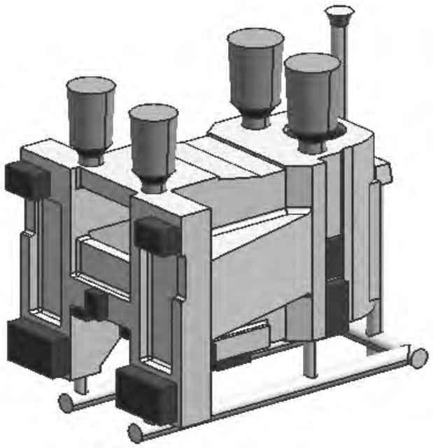
The sand mold casting of the spindle box of the machine tool is shown in Figure 1, with a maximum outer dimension of 475mm x 369 mm x 350 mm and a total weight of 101.16 kg. It belongs to the category of medium sand mold castings; The wall thickness difference at the shaft and barrel of sand castings is significant, with a maximum wall thickness exceeding 60 mm and a minimum wall thickness of only 10.5 mm. The process plan should avoid the generation of shrinkage holes, cracks, etc.
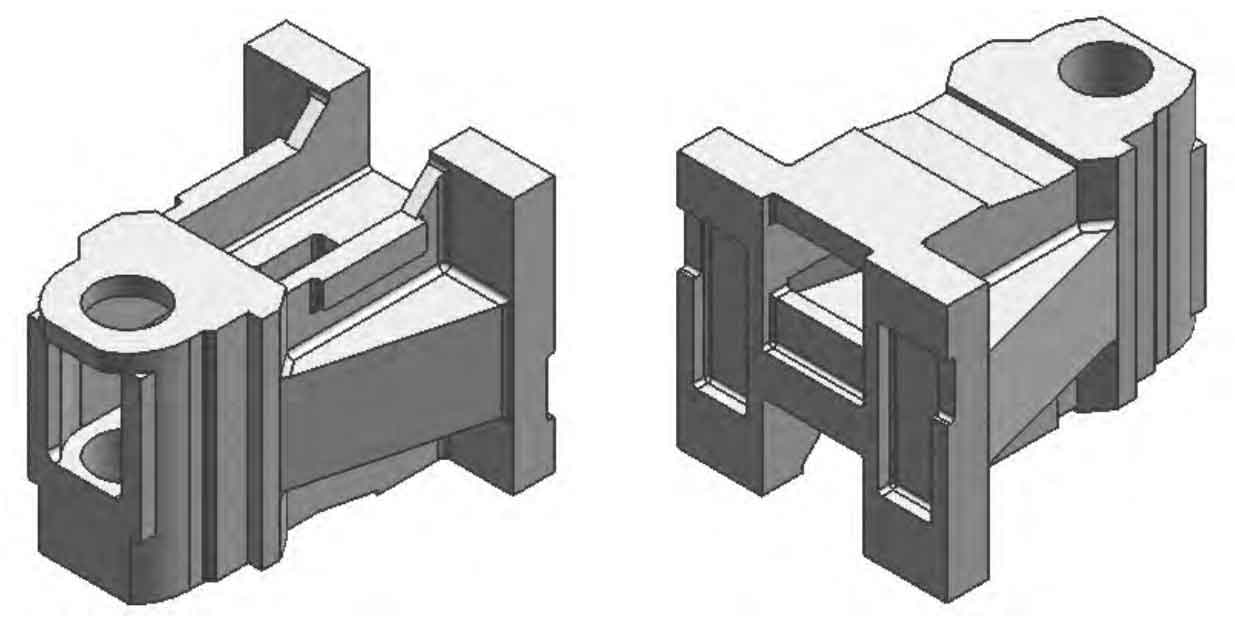
The material of the spindle box sand mold casting is HT300, and the specific chemical composition is shown in Table 1; The carbon equivalent of HT300 is about 3.558%, belonging to hypoeutectic sand cast iron with a eutectic degree of about 0.81. Its flowability is poor, and due to CE<3.6%, there is only shrinkage during the solidification of sand castings, which increases the tendency for shrinkage and porosity in sand castings. Therefore, in order to obtain high-quality sand castings, efforts should be made to improve the flowability of the molten iron and design a feeding system.
| Component | C | Si | Mn | P | S | Fe |
| Content | 2.90-3.20 | 1.40~1.70 | 0.80~1.00 | <0.15 | ≤0.12 | the rest |
2. Design of Sand Casting Process
2.1 Pouring position and parting surface
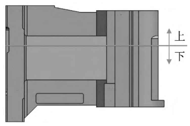
The wall thickness difference of the spindle box sand mold casting is significant, making it difficult to achieve simultaneous solidification. Therefore, the priority should be given to forming sequential solidification. Based on the structural characteristics of the spindle box sand mold casting, it is better to choose the pouring position shown in Figure 2; The parting surface is selected on the upper surface of the square hole of the shaft barrel, which is the maximum cross-section of the sand casting and has the least use of live blocks, making it easy to shape.
2.2 Design of pouring system
The formula for calculating the pouring time of sand cast iron parts with a pouring weight less than 450 kg and a complex structure is provided as formula (1):
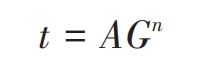
Where t is the pouring time; A. N is the empirical coefficient, with values of 1.8 and 0.5, respectively; G is the pouring weight, and the mass of the sand mold casting is 101.16 kg. By calculation, it is determined that the pouring time t is 18.10 seconds.
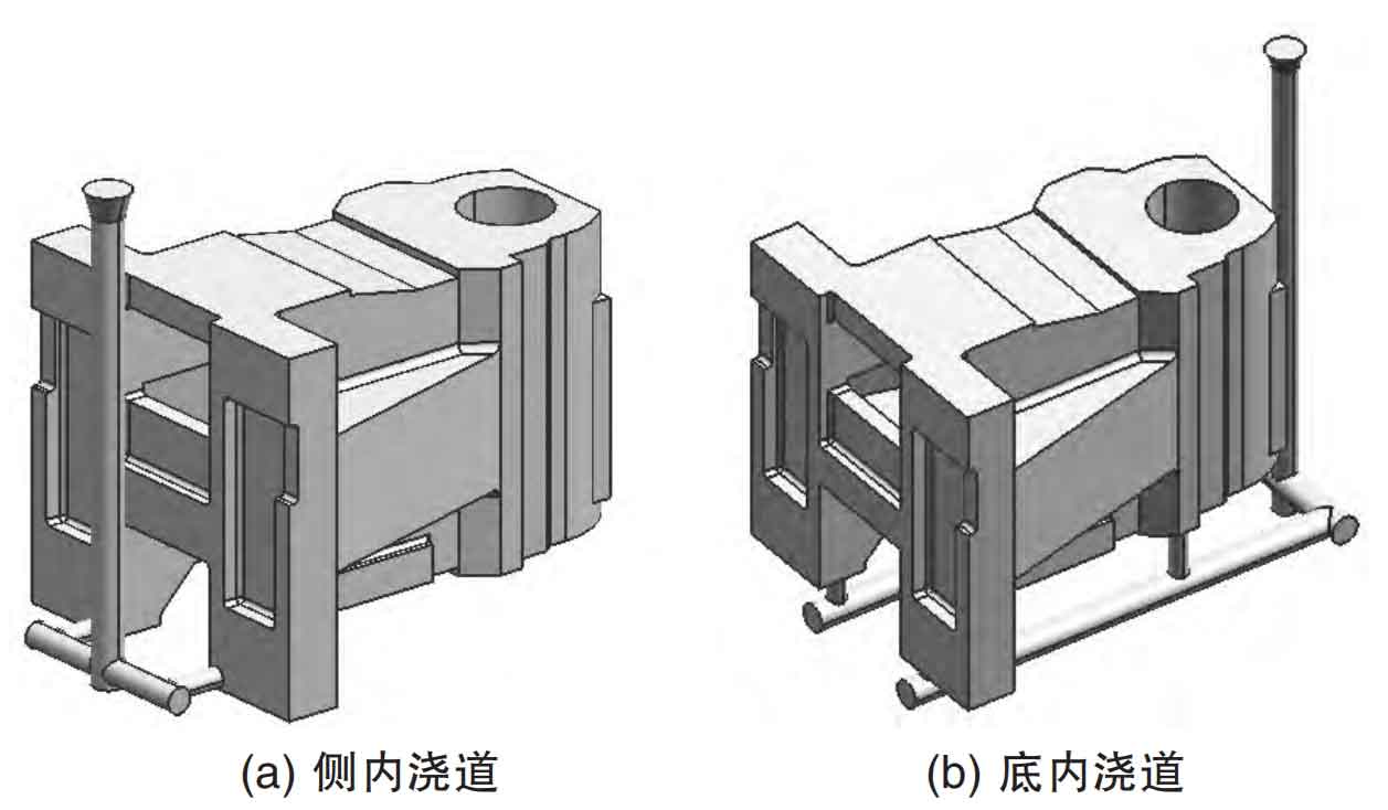
According to the characteristics of the spindle box sand mold casting, a semi closed gating system is adopted, with a gate ratio of ∑ A straight: ∑ A horizontal: ∑ A inner=1.1:1.5:1; From the perspective of facilitating smooth filling and avoiding impact and splashing, it is better to choose a bottom pouring system. According to the selection of pouring positions, there are multiple options for the opening of the inner pouring channel. Two preliminary schemes have been determined, as shown in Figure 3. Figure 3 (a) shows the side inner pouring channel, set as Scheme 1, and Figure 3 (b) shows the bottom inner pouring channel, set as Scheme 2. The size of the pouring channel is shown in Table 2. Due to the influence of the height of the sprue on the flow field of the molten metal and the amount of modeling materials, its height should be reasonably selected to meet the minimum remaining head height Hm requirement. Hm calculation is shown in formula (2):
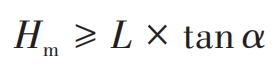
According to the arrangement of the pouring system, where L is approximately 572 mm, select the pressure angle α At 8 °, it can be calculated that Hm ≥ 80.39 mm. However, according to the selection of the parting surface, the height of the sand casting on the upper sand box is 131 mm. To ensure sufficient sand intake for the sand casting, the height of the sprue on the upper part of the parting surface is selected as 250 mm.
| Plan number | Number of straight pouring channels | Vertical sprue diameter/mm | Number of horizontal pouring channels | Horizontal sprue diameter/mm | Number of internal pouring channels | Inner sprue diameter/mm |
| 1 | 1 | 30 | 2 | 25 | 2 | 20 |
| 2 | 1 | 30 | 2 | 25 | 4 | 15 |
3. Numerical simulation and optimization
Analyze the two schemes using ProCAST numerical simulation technology and select the best one. The process plan establishes a 3D model through UG, imports it into ProCAST in. stp file format for mesh division, selects EN-GJL-300 (i.e. HT300) material, selects resin sand for casting, and sets other parameters as shown in Table 3.
| Parameter | Pouring temperature ℃ | Mold temperature ℃ | Air temperature ℃ | Pouring time s | Heat transfer coefficient W/(m ^ 2 · K) at the interface between castings and molds |
| Numerical value | 1350 | 20 | 20 | 18.10 | 500 |
3.1 Flow field simulation
The flow field simulation of the process plan is shown in Figure 4. From Figures 4 (a) – (1), it can be seen that the opened side inner runner produces a rotation phenomenon during the initial filling stage, and the metal liquid fills the bottom in a rotating state, which is prone to defects such as air entrainment and slag inclusion; And from Figure 4 (a) – (2), it can be seen that the two streams of molten metal flow forward along both sides of the cavity and intersect at the bottom of the shaft. The slender flow channel will cause the temperature of the molten metal to drop too quickly, and it is easy to form fusion marks at the intersection of the bottom of the shaft and barrel; In the subsequent flow, the metal liquid is filled and stabilized.
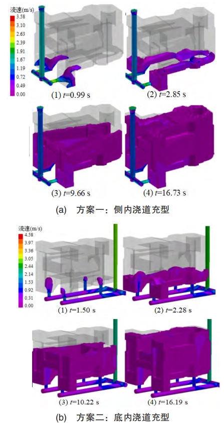
The filling of the bottom inner runner is shown in Figure 4 (b). Due to the vertical placement of the inner runner, the larger pressure head causes the metal liquid to produce a fountain phenomenon, as shown in Figures 4 (b) – (1), which is prone to defects such as pores; From Figures 4 (b) – (2), it can be seen that the uniform cross-section of the inner runner allows for faster and more filling of the metal liquid in the support seat, which can keep the liquid level at the far and near ends basically level, avoiding severe disturbance caused by the height difference of the liquid level; The subsequent filling process is relatively stable.
Combining the two, although both schemes have certain defects in the initial filling stage, the first scheme inevitably causes the metal liquid to rotate due to the structure of the sand casting, thereby deteriorating the quality of the sand casting and making it difficult to solve; Option 2 is due to the excessive pressure head causing fountain phenomenon. Therefore, measures only need to be taken to slow down the flow rate of the metal liquid and improve the fountain phenomenon to eliminate defects. Therefore, optimization of Option 2 is chosen.
3.2 Sprue optimization
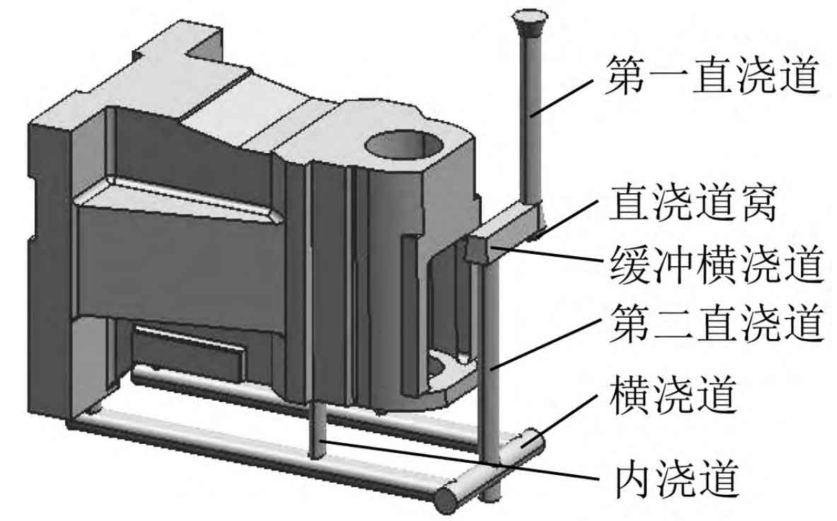
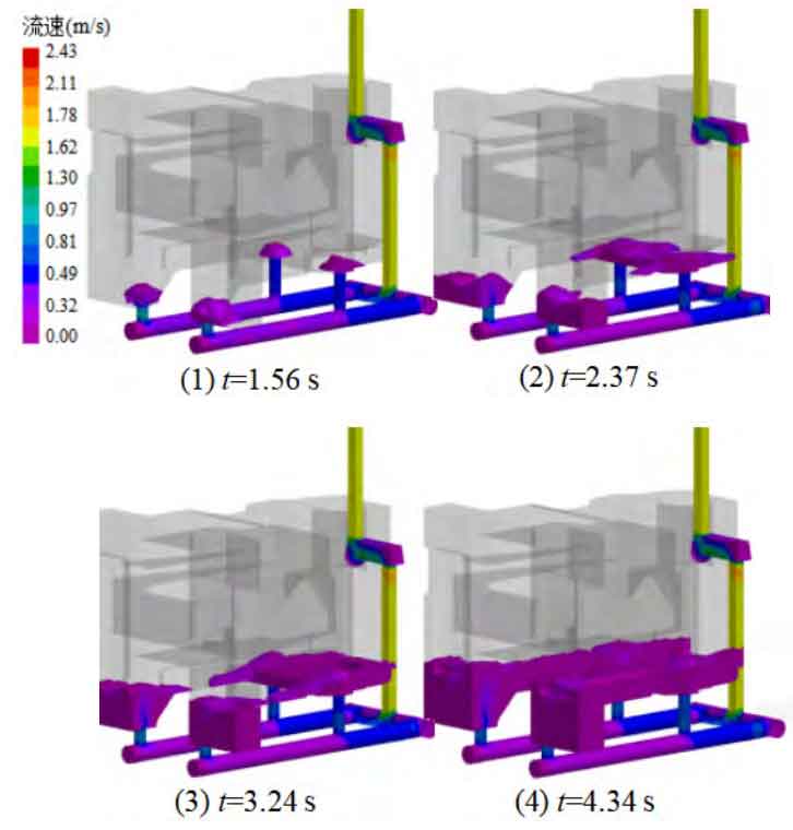
The fundamental reason for the rapid flow rate in Plan 2 is that the pressure head of the metal liquid at the beginning of entering the mold cavity is too large, and the height difference from the top of the sprue to the bottom of the sand mold casting is nearly 470 mm. During this period, the metal liquid can achieve a larger velocity under the action of gravity, resulting in the phenomenon of a fountain. For this reason, a buffer transverse gate has been introduced into the sprue. In order to have a better buffering effect, the cross-sectional area of the buffer transverse gate should be larger than that of the sprue, forming an open structure. Therefore, the cross-sectional area of the buffer transverse gate is selected to be 1.3 times that of the sprue; For the convenience of shaping and slag blocking, the buffer runner is set at the parting surface, as shown in Figure 5. This method divides the sprue into two parts. After the molten metal enters the pouring system through the first sprue, it is first buffered by the sprue nest and the buffering transverse sprue, and then buffered by the transverse sprue and inner sprue, which can effectively reduce the speed of molten metal entering the mold cavity and avoid the occurrence of fountain phenomenon. As shown in Figure 6, through numerical simulation analysis, the velocity of the metal liquid entering the mold cavity is around 0.49 m/s, which is about 50% slower than before optimization. The height of the metal liquid spraying is also greatly reduced, presenting a flat state, proving that the flow rate is appropriate and can ensure stable initial filling.
3.3 Temperature Field Simulation and Optimization
The simulated temperature field and defect distribution are shown in Figure 7. From Figure 7 (a), it can be seen that the pre optimized solution has collapsed at the top of the shaft, indicating insufficient self compensation; Moreover, the temperature at the four ends of the top and side walls of the shaft is relatively high, and the difference in wall thickness results in slower solidification. From the defect distribution in Figures 7 (a) – (2), it can be seen that shrinkage and porosity also occur at these positions, which need to be eliminated through the riser and cold iron process.
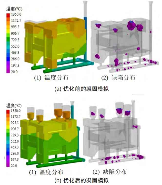
Due to the eutectic degree of HT300 being about 0.82, the feeding distance of its riser can reach about 8 times the diameter of the riser. Therefore, based on the structural dimensions of the spindle box sand mold casting, it is sufficient to set up four risers, including two at the top of the sidewall and two at the shaft barrel. The size of the riser is calculated using the modulus method, and the specific values are shown in Table 4. In addition, due to the large size of the hot spot in the sand mold casting of the spindle box, cold iron is required to achieve better shrinkage effect. Therefore, a total of 25 iron external cold irons are arranged in the hot spot areas such as the shaft barrel and side wall, as shown in Figure 8.
| Position | D size/mm | d size/mm | H size/mm | h size/mm |
| Axis cylinder section | 70 | 35 | 116 | 18 |
| Side wall section | 60 | 30 | 104 | 15 |
The solidification simulation of the optimization scheme is shown in Figure 7 (b). Compared with Figure 7 (a), it can be seen that in the optimization scheme, the temperature distribution of the sand casting shows a decreasing trend from top to bottom, and the highest temperature occurs in the riser; From the defect distribution in Figures 7 (b) – (2), it can be seen that shrinkage and porosity are concentrated in the pouring system, and almost no shrinkage or porosity is found on the sand mold castings, proving the rationality of the optimization plan. By using this plan, high-quality qualified sand mold castings can be obtained.
4. Conclusion
The wall thickness difference of the sand mold casting of the machine tool spindle box is significant, and the formation of sequential solidification should be the first consideration. At the same time, to ensure the filling effect of HT300, the best choice is to choose a semi closed bottom pouring runner.
Through numerical simulation, it was found that the opening of the side inner runner can cause the rotation of the molten metal, which is prone to defects such as gas entrapment and slag inclusion. On the other hand, the bottom inner runner can produce fountain phenomena and defects such as gas holes.
Adding a buffer transverse runner in the sprue can effectively reduce the speed of molten metal entering the mold cavity, thereby avoiding fountain phenomenon in the bottom sprue and ensuring smooth filling.
Simulating the temperature field, it was found that there are many hot spots in the spindle box sand mold castings, and the HT300 lacks self filling shrinkage. By using a riser and cold iron, the sand mold castings can form a good sequential solidification, avoiding the occurrence of shrinkage defects.