Firstly, it is necessary to analyze the three-dimensional structure of the complex thin-walled engine connecting shell components, analyze the structural characteristics of this component, and follow the
Design a suitable pouring system based on the structure of the component, and simulate and verify it using the pouring parameters in Chapter 3 The finite element method is used to explore whether using these pouring parameters will cause obvious macroscopic defects in castings. Then proceed with the component The CAFE method is used to simulate the changes in the microstructure of the component from the perspective of nucleation parameters. Secondly, based on CAFE Design an appropriate insulation time. Finally, prepare castings based on all designed process parameters and observe the castings visually
Whether there are obvious casting defects and comparing them with the simulation results of the CAFE method through metallographic testing is a validation of the CAFE method Is the calculation of grain size consistent with the experiment.
1. 3D model establishment
Use UGNX software to conduct 3D modeling of complex thin-walled engine connecting shell components. The overall 3D modeling is shown in Figure 4.1, and other perspectives are shown in Figures 4.2 (a) – (f). The basic structural description of the overall components is: size 216mm × 180mm × 240mm, the entire component is designed with an eccentric three-way structure, and the central part of the component is connected to the thin wall through a circular arc structure. The maximum diameter of the component is 137mm, and at least 70% of the surface wall thickness of the component is only 3.5mm. The transition between the flange and the aperture is 3.5-5mm Uniform transition treatment between them.
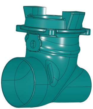
3D modeling diagram of complex thin-walled engine connecting shell components
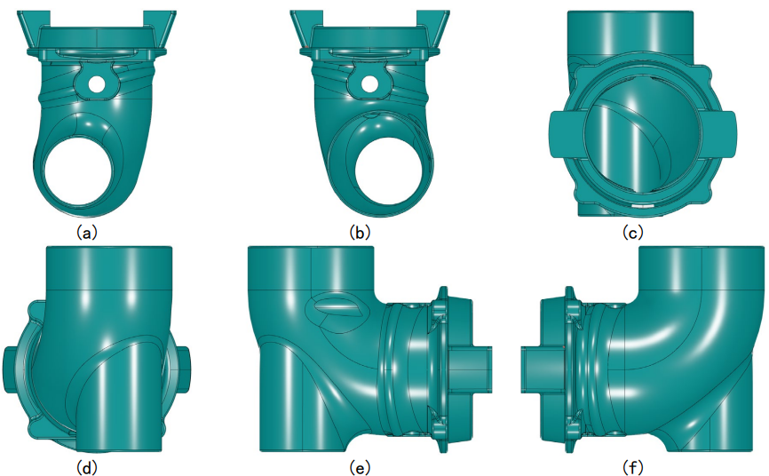
3D modeling from various angles
The entire component must be machined without any allowance, except for the flange part that requires simple machining Casting process design, and the thickest part of these areas is only 5mm. For this complex shape and extremely thin wall thickness, precision is required Choosing to use investment casting technology is a more effective and reliable casting method for components that are high in quality and require no margin for casting Manufacturing methods. The biggest advantage of investment casting compared to other casting processes is that it can ensure the dimensional accuracy of the castings,Generally, it can reach levels between CT4-6, while the commonly used sand casting dimensional accuracy is generally only between CT10-13 levels.However, there are many investment casting processes, and deviations in each stage can have an impact on the final casting result, especially shrinkage porosity
And shrinkage defects. So it is necessary to conduct simulation and analysis of important links in investment casting to reduce casting shrinkage and porosity The occurrence of hole defects.
2 Design pouring system
The design of the pouring system is the primary task in the entire pouring process design, as the setting of any pouring process parameters The existence of the pouring system must be considered in all calculations. A good pouring system can ensure that the metal liquid flows smoothly in the mold cavity and will not leak out There is an obvious defect of insufficient pouring, followed by the inevitable shrinkage caused by the solidification of the alloy liquid, which can be timely and effectively supplemented,To prevent shrinkage and porosity defects, the final step is to perform cutting work after pouring, which facilitates the separation between the pouring system and the casting.The design of the pouring system can be roughly approached from three perspectives: pouring method; Pouring parameters and the shape of the pouring pipeline And size.
Because considering the size and weight of the component, especially in the shell manufacturing process, the entire pouring system It must have sufficient strength, provide support for the shell, and also prevent the occurrence of insufficient pouring. Final selection Using a gating system with a transverse sprue morphology, this system can balance the shrinkage of the entire casting and the support of the mold shell. Afterwards, it is necessary to
To design the size of the pouring riser, attention must be paid to the presence of hot spots in the casting.
Considering that the transition groove between the thin-walled part of the component and the flange is prone to generating hot spots, in order to facilitate the size of the hot spot
Calculate and attribute the morphology of this area to a side length of a × B rectangle. Reuse the equivalent heat node calculation chart to calculate the equivalent heat node at that location
The diameter is [88], and the equivalent hot spot diameter at the inclined groove is 𝐷𝐷𝑐𝑐𝑐=200mm.
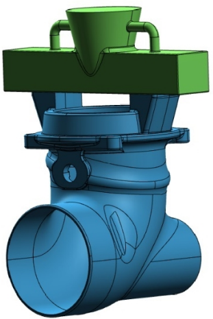
Connection diagram between pouring system and engine connecting shell components
The weight of the entire component, including the pouring system, that needs to be filled is about 13kg. According to the pouring speed of 3.5kg/s, the pouring time is about 3.714s. The red part in Figure 5.4 represents the alloy liquid, and (a) – (c) show the specific position of the alloy liquid front in the casting cavity at different filling times.
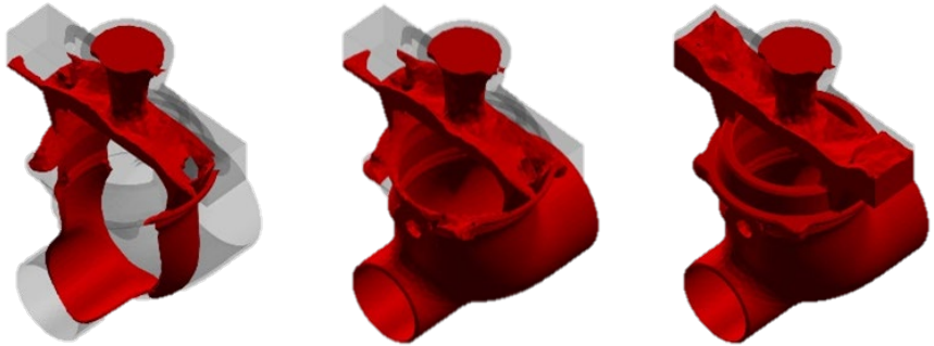
State diagram of alloy liquid filling process at different times of casting
The alloy liquid begins to solidify at the bottom of the casting, with a wall thickness of only 3.5mm. The thinner the casting wall, the better the heat dissipation effect, so this area has good heat dissipation ability and reduces the time required for solidification.
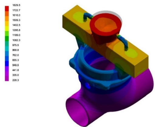
Schematic diagram of solidification time at different positions of castings
3 Numerical value of solidification defects
Sequential solidification results in different solidification times in different parts, which inevitably leads to shrinkage and porosity of casting defects Appears. In the actual casting process, there are often large and concentrated holes in the final solidification area, which are A hole is called a shrinkage cavity, and its formation is mainly due to the fact that the liquid phase shrinkage rate of the alloy is usually greater than the solid phase shrinkage rate of the alloy Shrinkage rate. Meanwhile, during the solidification process of the alloy, some small and dispersed pores may appear, which are called shrinkage pores The main reason for the occurrence of looseness and shrinkage is that when a liquid phase of the same mass is transformed into a solid phase, the difference in density will cause the volume to change
Slight contraction. If the liquid alloy liquid is not timely replenished and shrunk in this area, small dispersed pores will appear, which is shrinkage Pine. Shrinkage and porosity can cause serious damage to the various properties of castings. For example, the effective bearing area of the casting material will
When reduced, stress concentration will occur in the vicinity of defects. For stainless steel alloys under investment casting technology, It will also reduce the corrosion resistance of the material and deteriorate the surface smoothness.To analyze shrinkage porosity, it is necessary to analyze the filling capacity of the pouring system, which is the probability of insufficient casting. The smaller the probability,The smoother the pouring process, the better the filling and shrinking ability; conversely, it indicates that there is an unreasonable design in the pouring system, and the filling and shrinking ability is improved
To be strengthened. Especially for complex thin-walled castings, once the phenomenon of insufficient pouring occurs, it is likely to lead to the entire casting Scrap and turn into waste. For investment casting, which takes a long time and incurs high costs, insufficient pouring is a disadvantage Sinking must be avoided. Figure 4.6 simulates the probability of insufficient pouring in various parts of the casting.
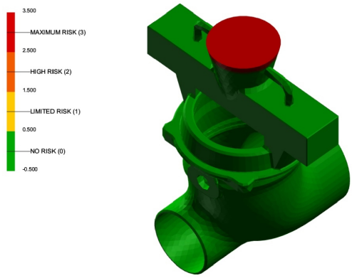
Schematic diagram of the probability of insufficient pouring in various parts of the casting
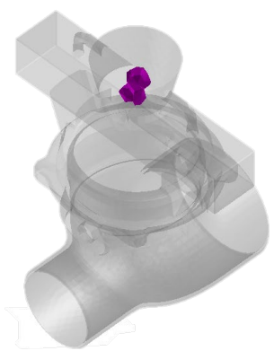
From the figure, it can be seen that shrinkage only occurs at the riser in the pouring system, and there are no obvious casting defects inside the engine connecting shell components, avoiding unnecessary material waste. This simulation demonstrates that the design of the gating system and casting process parameters is reasonable for the shrinkage problem.
