
The gating system of lost foam casting is different from the traditional sand casting, and should be as simple as possible. Because there are many inner holes in the valve body structure, the distribution is relatively complex, and the wall thickness is uneven, the top pouring and side pouring can be used. The top-pouring pouring structure is simple and has no transverse runner. In order to ensure the smooth completion of the filling process, the pouring temperature should be higher than its liquidus temperature during the filling process. The simulation results of the lost foam casting after the completion of top-pouring filling are shown in Figure 1.
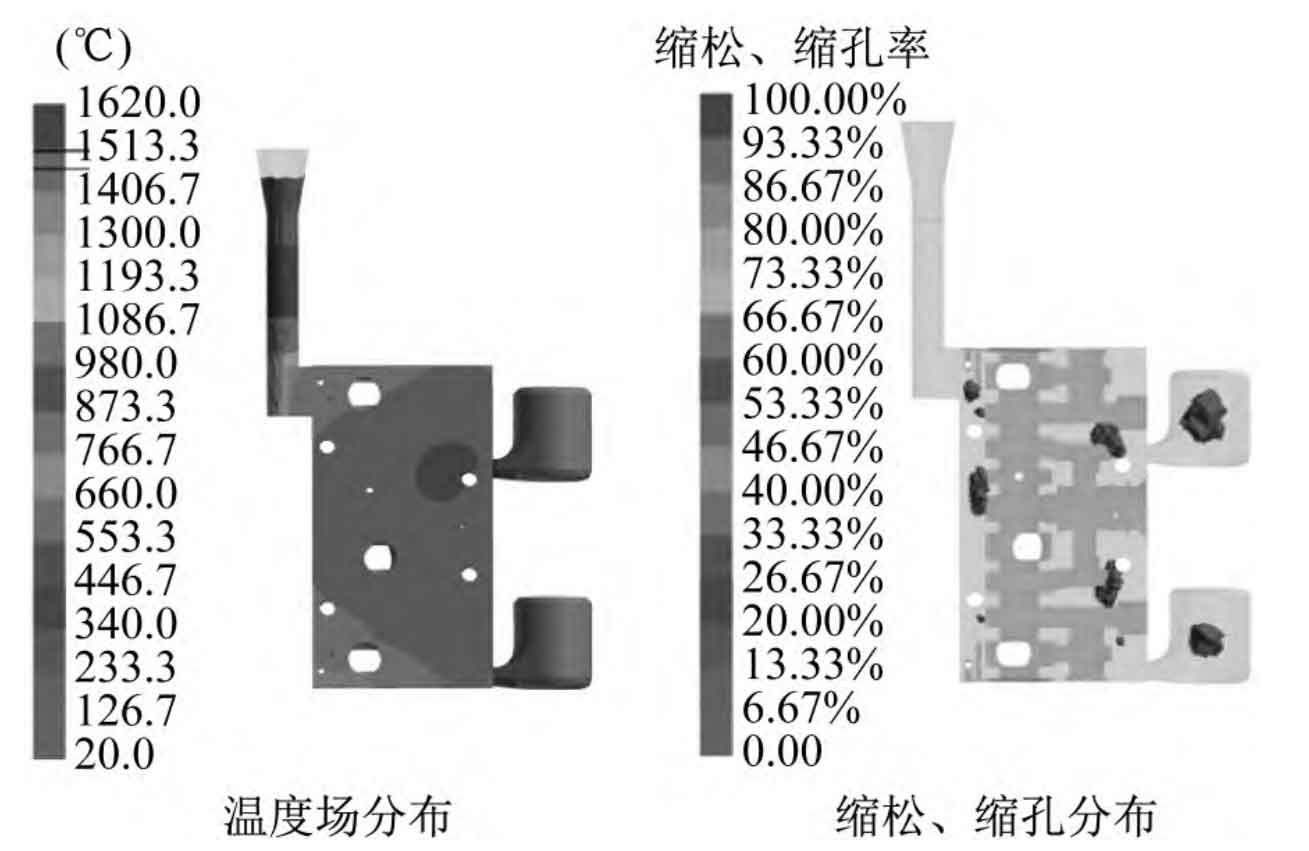
It can be found that the temperature field distribution of the lost foam casting is non-uniform, and the temperature difference is obvious everywhere. The temperature in the area near the locating hole at the upper right of the lost foam casting is high, which affects the solidification of the lost foam casting, and is difficult to meet the principle of sequential solidification. This non-uniform solidification will cause non-uniform volume shrinkage of the lost foam casting, which can lead to shrinkage porosity and shrinkage cavity in the lost foam casting. Shrinkage porosity and shrinkage cavity are scattered in the interior of the lost foam casting, and appear in the area with large wall thickness of the lost foam casting. This is because the temperature is high here, the cooling is slow during solidification, and it is difficult to feed.
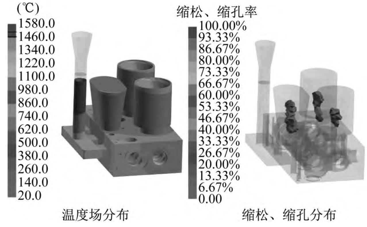
Because the determination of pouring type and position has a great impact on the smooth filling and solidification of lost foam casting, a reasonable pouring method should be able to eliminate shrinkage porosity and shrinkage cavity. As mentioned earlier, it is difficult to fill the lost foam casting of the top-pouring pouring system, which is prone to shrinkage porosity and shrinkage cavity. Through the analysis of the valve body structure, the side gating system with three transverse runners is designed at the place where the local wall thickness of the lost foam casting is relatively large, and three risers are set according to the possible hot spot position and structure of the lost foam casting. The simulation results of the lost foam casting after the completion of the filling of the side injection casting are shown in Figure 2. It can be seen that the temperature of lost foam casting is relatively low as a whole, and the riser and riser attachment area are the final solidification positions, basically meeting the principle of sequential solidification of lost foam casting. Due to the improvement of the riser and pouring method, shrinkage porosity and shrinkage defects in the lost foam casting in this pouring scheme remain in the riser, and a defect-free lost foam casting is obtained.