

1. Introduction
Lost foam casting is a modern casting process that has gained significant popularity due to its numerous advantages. It offers excellent surface finish, high dimensional accuracy, and a relatively high process yield. Ductile iron, with its good mechanical properties such as high strength, toughness, wear resistance, and shock resistance, is widely used in various applications. In this study, we focus on the production of ductile iron reducer housings using the lost foam casting process and address the issues of wrinkling and shrinkage defects.
1.1 The Significance of Lost Foam Casting
Lost foam casting eliminates the need for a separate mold cavity, as the foam pattern is directly used for casting. This reduces the complexity and cost associated with traditional casting methods. The process allows for the production of complex geometries with ease, making it suitable for a wide range of components.
1.2 Ductile Iron Properties and Applications
Ductile iron, also known as nodular cast iron, has a graphite structure in the form of nodules. This unique structure imparts excellent mechanical properties, making it suitable for applications where strength and toughness are required. It is commonly used in automotive components, machinery parts, and structural applications.
2. The Original Process of Ductile Iron Reducer Housing Casting
2.1 The Pouring System and Process Parameters
The original pouring system of the reducer housing is shown in Figure 1. The end face has a designed process allowance of 4 mm. The furnace temperature ranges from 1580 to 1600 °C, the pouring temperature is between 1370 and 1440 °C, the pouring negative pressure is -0.06 to -0.04 MPa, and the negative pressure holding time is 900 s. The chemical composition of the reducer housing is presented in Table 1.
| Main Elements | Si | Mn | P | S | Mg | RE | |
|---|---|---|---|---|---|---|---|
| Content | 3.5 – 4.0 | 2.0 – 3.0 | ≤0.45 | 0.05 | 0.025 | 0.02 – 0.06 | 0.015 – 0.04 |
2.2 Mechanical Properties and Defects
The Y – type specimen mechanical properties meet the requirements of QT450 – 10, and the nodularization rate of 2 – 3 levels also conforms to the technical requirements of the ductile iron reducer housing. However, during the trial production of the reducer housing using lost foam casting, defects such as wrinkling, shrinkage porosity, and shrinkage holes were observed. In particular, wrinkling on the end face and shrinkage holes at geometric hot spots were significant during small – batch production.
3. Formation Causes of Wrinkling and Shrinkage Defects
3.1 Wrinkling Formation Causes
3.1.1 Carbon Defect and Foam Material Selection
In ductile iron casting, carbon content generally ranges from 3.5% to 3.8%, which makes it prone to carbon defects. Considering both gas generation and carbon content, a copolymer material is chosen for the ductile iron white model. This copolymer material balances the gas generation and solid carbon content of EPS and EPMMA, reducing the likelihood of carbon defects and the risk of porosity in the casting.
3.1.2 Influence of Pouring System Structure
The original pouring system of the reducer housing is a top – pouring design, which is actually a kind of middle – bottom pouring process using the cavity as a runner. During the pouring process, the high – temperature iron liquid enters the top surface of the white model from the inner gate and does not fill the cavity gradually from top to bottom. Instead, it directly penetrates the thick wall area at the top, uses the top of the cavity as a runner, and then fills the thin wall area in a fan – shaped manner downward. After reaching the bottom, it fills upward again, resulting in a turbulent middle – bottom pouring filling mode. This causes the thick and large dead corner areas at the top and side to form “cold ends”, leading to wrinkling defects.
3.2 Shrinkage Hole Formation Causes
3.2.1 Alloy Properties and Requirements
From the perspective of the carbon equivalent of ductile iron, the chemical composition of the reducer housing meets the requirements as the Y – type specimen mechanical properties and nodularization rate satisfy the technical requirements. Also, from the surface quality observation of the ductile iron reducer housing, there are no cold shuts or sand sticking problems, eliminating the influence of nodularization treatment temperature, pouring temperature, and negative pressure on the shrinkage holes of the reducer housing.
3.2.2 Lack of Feeding and Geometric Hot Spots
The fundamental cause of shrinkage holes in ductile iron castings is that during liquid contraction and solidification, a certain part of the casting (usually the hot spot that solidifies last) cannot receive timely liquid metal feeding, resulting in irregularly shaped holes with rough hole walls at that location. In the case of the reducer housing, the shrinkage hole defects mainly exist in the thick positions of the side processing holes, which are mainly caused by geometric hot spots. Therefore, to solve the shrinkage hole defect of the reducer housing, it is necessary to start from the casting process, change the cooling structure of the casting, increase the heat dissipation surface area, reduce the local modulus, and eliminate the geometric hot spots of the casting.
4. Solutions and Verifications for Defects
4.1 Solutions for Wrinkling Defects
4.1.1 Redesign of the Pouring System
The wrinkling defect of the reducer housing is mainly due to the unreasonable design of the pouring system, which forms a middle – bottom pouring filling mode, causing turbulent flow of the iron liquid during pouring and resulting in wrinkling defects on the casting surface. To solve this problem, the pouring system is redesigned to a bottom – pouring system as shown in Figure 2. The filling process is a pure bottom – pouring mode, where the high – temperature iron liquid fills the cavity steadily from the bottom upward. As a result, the low – temperature iron liquid at the front end and the products of insufficient gasification of the white model stay at the processing allowance position on the top surface of the cavity, producing a casting with a sound surface.
4.1.2 Theoretical Calculations and Design Details
The pouring time is calculated as
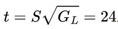
. The height of the average static pressure head for bottom injection is calculated as :
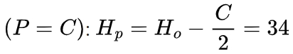
cm. The minimum cross – sectional area of the inner runner is calculated as
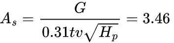
cm². According to experience and relevant charts, the cross – sectional area of the inner runner in lost foam casting is generally slightly larger than that of sand casting. Based on the casting structure, the newly designed inner runner is a central pouring type with four inner gates, each with a cross – sectional dimension of 7 mm × 40 mm, and the total cross – sectional area of the four inner gates is 11.2-12.8 cm². The length of the straight runner is designed as 480 mm with a pressure head of 200 mm.
4.1.3 Verification Results
After redesigning the casting process and using the new bottom – pouring system, 2000 pieces were produced in batches for verification. The results showed that the surface quality of the castings produced by the new casting process was qualified, and no batch wrinkling defects occurred on the surface, as shown in Figure 3.
4.2 Solutions for Shrinkage Hole Defects
4.2.1 Traditional Solutions and Their Limitations
Traditional solutions for shrinkage hole defects include setting risers at hot spots to provide the necessary metal liquid for compensation during casting formation and using a chilling system, usually with chills to form an artificial end zone at the hot spot, creating a sequential solidification to eliminate shrinkage holes. However, for the lost foam casting of the reducer housing, these methods have limitations. Adding risers reduces the process yield of the reducer housing casting and increases the overall process complexity. Using the chill process, due to the characteristics of lost foam casting, the chills are prone to falling off during molding and may cause casting deformation, resulting in high process difficulty, significant impact on the quality stability of the reducer housing, and increased casting costs.
4.2.2 The New Heat Dissipation Process
A new lost foam casting process, the heat dissipation process, is developed to address the shrinkage hole problem of ductile iron hot spots. The core purpose of this process is to change the casting structure, increase the heat dissipation surface area, reduce the modulus at the hot spot of the casting, and allow the negative pressure gas to carry away a large amount of heat during the solidification stage, achieving a chilling effect.
4.2.3 Application and Verification of the Heat Dissipation Process
In the production of the reducer housing, 12 heat dissipation sheets with dimensions of 50 mm × 30 mm × 7 mm are bonded in the hot spot area of the casting during the cutting and bonding process. Other process steps remain unchanged. After trial production and machining verification, the bolt holes of the reducer housing are normal and have no quality problems. After using the heat dissipation process for batch production of 2000 reducer housings, no batch shrinkage hole defects were observed in the bolt holes after machining.
5. Conclusion
5.1 Summary of Defect Solutions
- By optimizing the pouring system to ensure a stable filling process during pouring and using the process allowance to collect the iron liquid with impurities at the front end, the wrinkling defect of the casting is solved.
- For the shrinkage holes caused by hot spots in lost foam casting of ductile iron, a new heat dissipation sheet process is designed. By setting a certain number of heat dissipation sheets at the hot spots of the casting, the local heat dissipation speed is enhanced, the geometric hot spots of the casting are eliminated, and the shrinkage hole defect of the casting is solved. This heat dissipation sheet process has been verified in the practice of reducer housing castings and proven to meet the design requirements and solve the shrinkage hole defect.
5.2 Significance and Future Prospects
The solutions presented in this study for wrinkling and shrinkage hole defects in lost foam casting of ductile iron reducer housings provide practical methods for improving the quality of castings. These methods not only solve the existing problems but also offer a reference for similar casting processes. In the future, further research can be conducted to optimize the process parameters and explore more efficient defect prevention and control measures to continuously improve the quality and performance of lost foam casting products.
In conclusion, lost foam casting of ductile iron has great potential in industrial applications. By addressing the challenges of wrinkling and shrinkage hole defects, we can enhance the reliability and competitiveness of ductile iron castings produced by this process.